
Artificial spinal disc implant

a technology of spinal disc and implant, which is applied in the field of artificial spinal disc implants, can solve the problems of limiting the ability of the nucleus, affecting the function of the spinal disc,

Inactive Publication Date: 2009-10-29
RANIER LIMITED
View PDF51 Cites 18 Cited by
  • Summary
  • Abstract
  • Description
  • Claims
  • Application Information

AI Technical Summary

Benefits of technology

[0012]For purposes of clarity, not every component is labeled in every figure. Nor is every component of each embodiment of the invention shown where illustration is not necessary to allow those of ordinary skill in the art to understand the invention. All patent applications and patents incorporated herein by reference are incorporated by reference in their entirety. In case of conflict, the present specification, including definitions (if any), will control.

Problems solved by technology

A spinal disc may be damaged due to trauma, disease or other degenerative processes that can occur over time.
For example, the annulus fibrosis may weaken and / or begin to tear which can result in the protrusion of the nucleus pulposus into a region of the spine (e.g., the vertebratal foramen) that includes spinal nerves.
The protruding nucleus pulposus may press against spinal nerves causing pain, numbness, tingling, diminished strength and / or a loss of motion.
Such fluid loss can limit the ability of the nucleus pulposus to distribute stress and may reduce its height which can lead to further instability of the spine, as well as decreasing mobility and causing pain.
Though this technique may initially alleviate pain and can improve joint stability, it also can result in the loss of movement of the fused vertebral joint.
However, in general, such disc implants have been limited in their ability to adequately mimic the biomechanics of a normal healthy human spinal disc.
For example, such implants may not exhibit an appropriate resistance to the forces (e.g., bending, torsion, tension and compression) normally exerted on the implant throughout the day.
As a result, these implants may not effectively perform the functions of a natural spinal disc.
Also, the implants may be prone to failure and / or may be dislodged from their position within the spine.

Method used


Image

  • Artificial spinal disc implant
  • Artificial spinal disc implant
  • Artificial spinal disc implant

Examples


Embodiment Construction

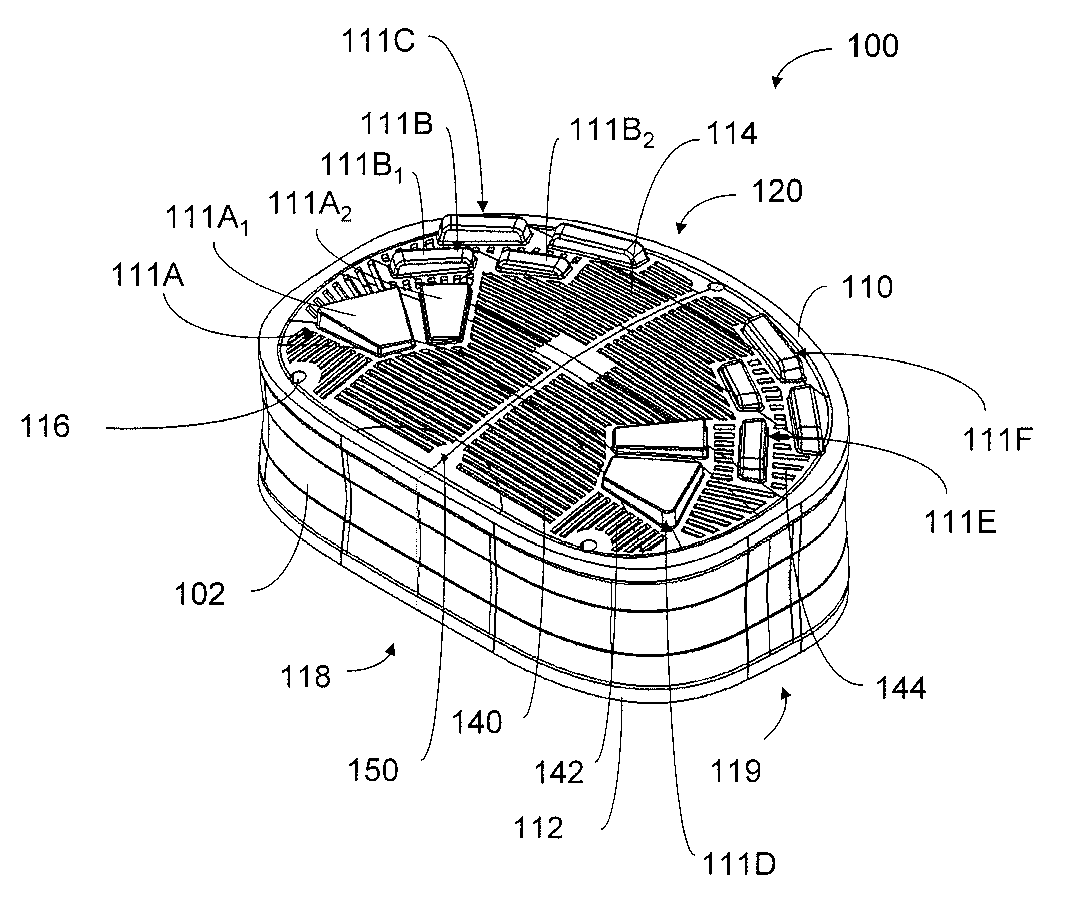
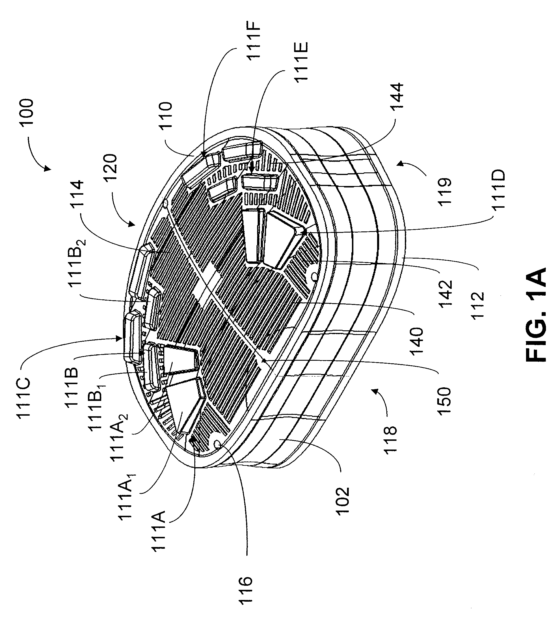
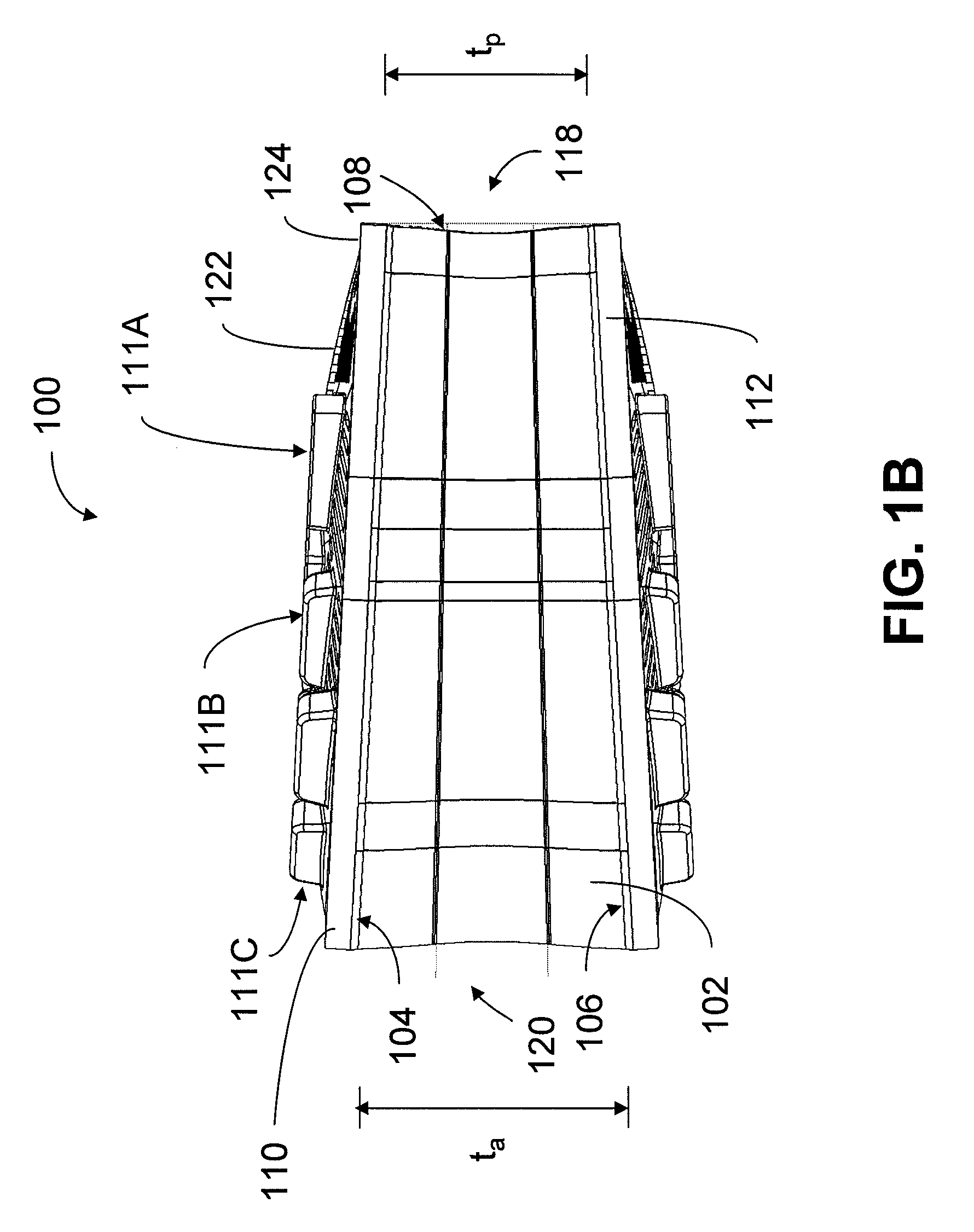
[0023]An artificial spinal disc implant is provided that may be implanted between adjacent vertebrae in the spine to replace, repair or augment a natural spinal disc. The spinal disc implant may be characterized by one or more biomechanical properties that approximate those of a natural spinal disc. The implant is also designed to be sufficiently secured to the vertebrae so that it may function in the body for long time periods.

[0024]The disc implant may include one or more end plates. The end plates may have an outer surface that includes fixation elements that are designed to fit into corresponding features (e.g., recesses) on the vertebrae to secure the disc between the vertebrae. The fixation elements may be arranged and configured to provide a greater resistance to forces that act to dislodge the disc from its position between the vertebrae. For example, the fixation elements may be designed to have certain preferred dimensions and / or may be positioned in certain preferred arra...


PUM


Abstract

An artificial spinal disc implant is provided that may be implanted between adjacent vertebrae in the spine to replace, repair or augment a natural spinal disc. The spinal disc implant may be characterized by one or more biomechanical properties that approximate those of a natural spinal disc. The implant is also designed to be sufficiently secured to the vertebrae so that it may function in the body for long time periods.

Description

RELATED APPLICATIONS[0001]This application is a continuation-in-part of U.S. patent application Ser. No. 12 / 108,698, filed Apr. 24, 2008, entitled “Artificial Spinal Disc Implant” which is incorporated herein by reference.FIELD OF INVENTION[0002]The present invention generally relates to artificial spinal disc implants.BACKGROUND OF INVENTION[0003]A spinal disc lies between adjacent vertebrae in the spine. The disc stabilizes the spine and assists in distributing forces between vertebral bodies. A spinal disc includes an outer annulus fibrosis which surrounds an inner nucleus pulposus. The annulus fibrosis is a concentrically laminated structure of aligned collagen fibers and fibro cartilage which provides stability to resist axial torsional and bending forces. The nucleus pulposus comprises a gelatinous material which can distribute stresses acting on the disc.[0004]A spinal disc may be damaged due to trauma, disease or other degenerative processes that can occur over time. For exa...

Claims


Application Information

Patent Timeline
Patent Type & Authority Applications(United States)
IPC IPC(8): A61F2/44
CPCA61F2/30771A61F2/442A61F2002/30014A61F2002/3008A61F2002/30112A61F2002/30563A61F2250/0098A61F2002/30884A61F2002/30894A61F2002/3092A61F2230/0004A61F2250/0018A61F2002/30827A61B17/70A61F2/44
Inventor SNELL, ROBERT A.JOHNSON, SCOTTLAWSON, JONATHAN
Owner RANIER LIMITED
Learn More