Spinal implant and cutting tool preparation accessory for mounting implant

A technology of implants and tools, applied in the direction of spinal implants, bone implants, joint implants, etc., can solve the problems of bone fusion, insufficient insertion, etc.

Inactive Publication Date: 2002-11-13
SDGI HLDG
View PDF4 Cites 4 Cited by
  • Summary
  • Abstract
  • Description
  • Claims
  • Application Information

AI Technical Summary

Problems solved by technology

Therefore, spinal implants can neither be inserted too far into the openings provided in the cortical endplates to provide a sufficiently dense load-bearing surface

Method used


Image

  • Spinal implant and cutting tool preparation accessory for mounting implant
  • Spinal implant and cutting tool preparation accessory for mounting implant
  • Spinal implant and cutting tool preparation accessory for mounting implant

Examples


Embodiment Construction

[0039] In order to promote an understanding of the principles of the invention, reference will now be made to the embodiment illustrated herein and specific language has been used to describe the embodiment. Nevertheless, it should be understood that no limitation of the scope of the invention is intended. Any alterations and further modifications in the described processes, systems, or devices, as well as any further applications of the inventive principles described herein, will be within the contemplation of one of ordinary skill in the art to which the invention pertains.

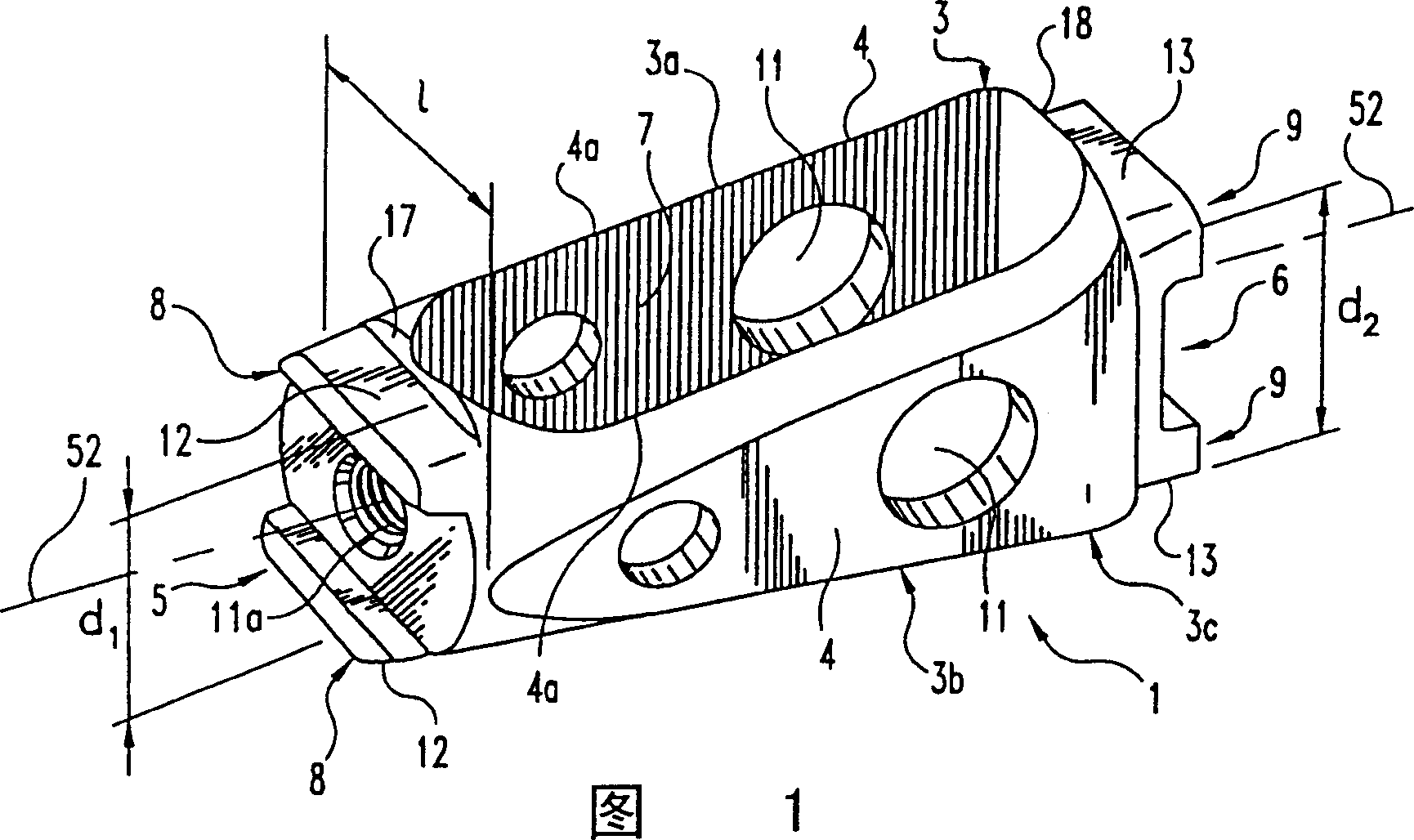
[0040] 1 , 6 and 7 depict a spinal cage implant 1 . The implant 1 is suitable for being inserted into the damaged intervertebral disc 2 ( Figure 7 ) in order to restore the two vertebrae V1 and V2 near disc 2 (e.g. Figure 7 Normal height of intervertebral space between lumbar vertebrae L3, L4) shown. FIG. 1 shows the implant 1 arranged along its longitudinal axis 52 . The implant 1 comprises: a ho...


PUM


Abstract

This invention relates to a spinal implant (110) for promoting fusion of adjacent vertebrae and restoration of normal disc height. The spinal implant includes an upper and lower surface (120, 122) adapted to engage cancellous bone tissue in the vertebral bodies. The spinal implant also includes at least two opposing bearing surfaces (138, 140) adapted to bear against cortical bone tissue in the endplates of adjacent vertebrae. This invention also provides an instrumentation to prepare the intervertebral space to receive the spinal implant and techniques for treating patients in need of corrective spinal surgery. <IMAGE>

Description

[0001] Related applications for reference [0002] This application claims priority to US Application No. 09 / 420,622, filed October 19, 1999, the entire contents of which are incorporated herein by reference. technical field [0003] The present invention relates generally to spinal implant devices, surgical tools, and related techniques for facilitating spinal fusion. Background technique [0004] It is well known that when intervertebral discs are degenerated or damaged, the discs are often compressed and the normal intervertebral height is reduced. Generally, the condition results in abnormal displacement that is the source of pain. [0005] To treat this pathology, the disc is usually stabilized to eliminate abnormal displacement caused by misalignment or injury of the disc. Generally, one approach is to use bone fusion to prevent coupling between the two vertebrae on each side of the damaged disc. This fusion fixes the vertebrae to each other, eliminating pain from r...

Claims


Application Information

Patent Timeline
IPC IPC(8): A61B17/56A61B17/58A61F2/00A61F2/28A61F2/30A61F2/44A61F2/46A61L27/00A61L31/00
CPCA61F2/28A61F2/442A61F2/4455A61F2/4465A61F2/4611A61F2002/2835A61F2002/30266A61F2002/30576A61F2002/30774A61F2002/30777A61F2002/30785A61F2002/30789A61F2002/448A61F2230/0082A61F2310/00017A61F2310/00023A61F2310/00179A61F2310/00359A61F2002/30261A61F2002/30593A61F2002/30845
Inventor 刘明岩D·肖邦汉斯-约尔格·迈泽尔
Owner SDGI HLDG
Why Eureka
Try Eureka