Spinal Implant, Instrument for Preparation and Method of Use

a technology for spinal cord and implant, applied in the field of spinal cord implants, can solve the problems of large back pain with or without leg pain, long recovery time for posterior surgery procedures, and complicated subsequent surgeries, and achieve the effect of maximizing the fusion mass

Active Publication Date: 2014-11-13
FBCDEVICE
View PDF8 Cites 8 Cited by
  • Summary
  • Abstract
  • Description
  • Claims
  • Application Information

AI Technical Summary

Benefits of technology

[0019]An objective of the present disclosure is to enable certain motions after surgery so that the patient, due to anatomy, muscle forces and more generally posture and spinal balance, may determine an appropriate position for spinal fusion. While allowing motions, the apparatus and associated methods of the present disclosure advantageously provide certain limits on motions and also provide resistive forces to certain o...

Problems solved by technology

Back pain with or without leg pain is a major problem in the adult population.
However, posterior surgery procedures are unfortunately associated with a long recovery compared to exclusively anterior surgery.
If the position is not correct, the surgery may result in a non-union (a failure to achieve fusion) or may even result in secondary effects caused by stress placed on the neighboring discs.
If necessary, subsequent surgeries are complicated by the previous surgery.
The lack of constraint in such unconstrained designs may prevent excessive facet joint or capsuloligamentous loads in the extremes of flexion and extension.
Furthermore, since the IAR is mobile, the unconstrained designs may be less sensitive t...

Method used


Image

  • Spinal Implant, Instrument for Preparation and Method of Use
  • Spinal Implant, Instrument for Preparation and Method of Use
  • Spinal Implant, Instrument for Preparation and Method of Use

Examples


Embodiment Construction

)

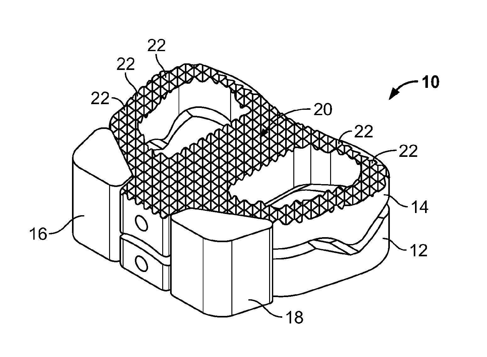
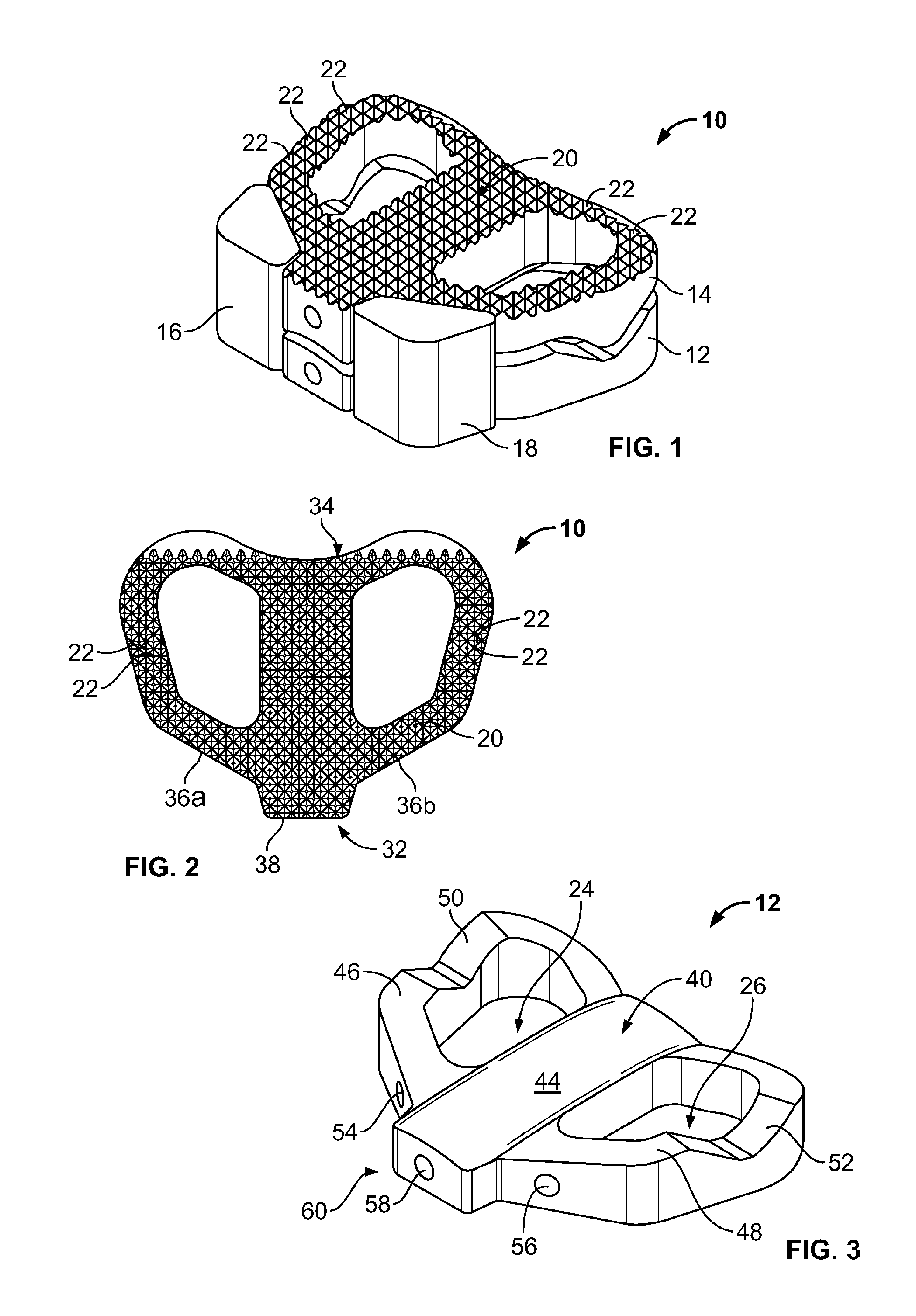
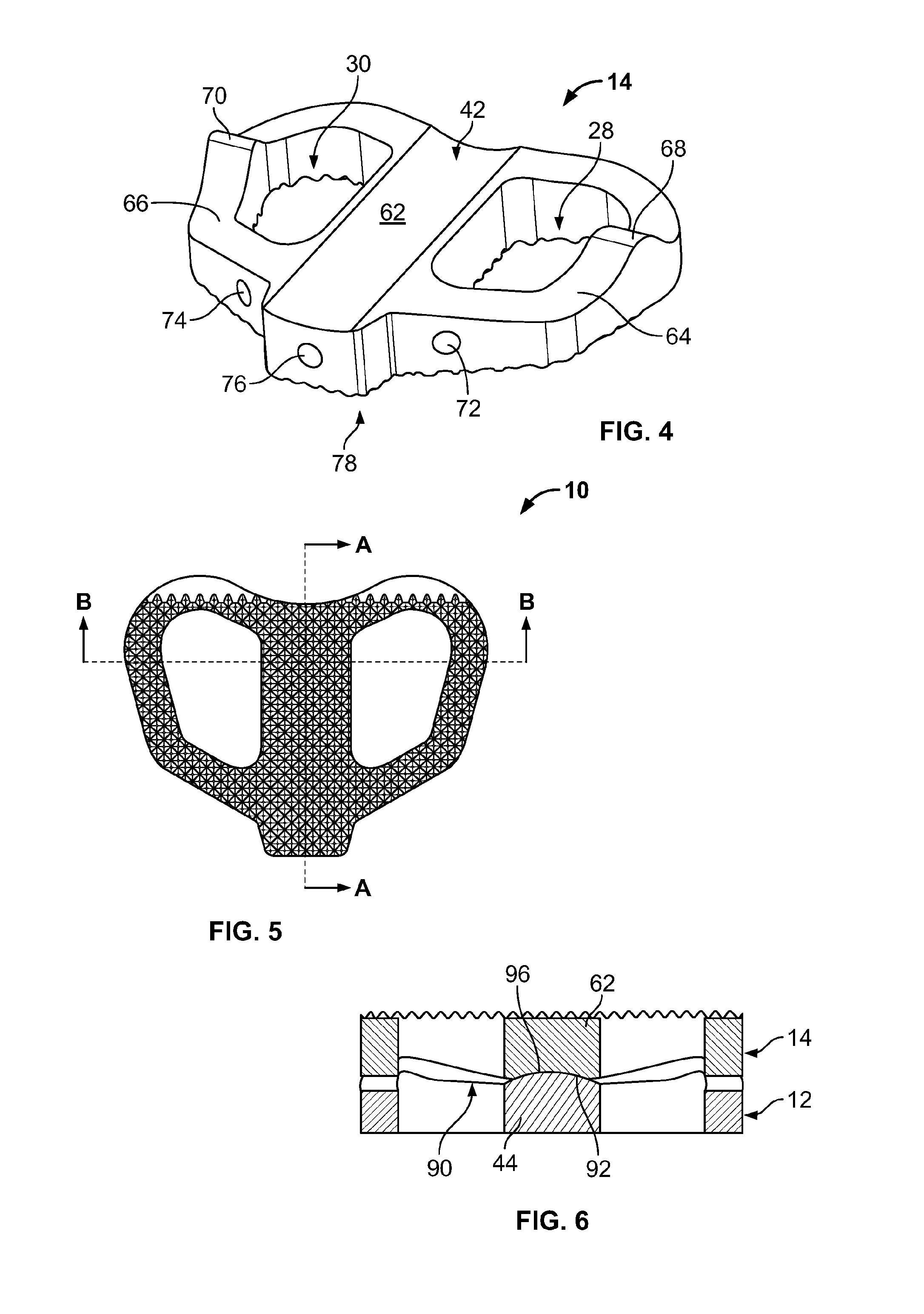
[0061]The present disclosure is directed to spinal disc implants for use in spinal procedures, e.g., cervical, thoracic and / or lumbar procedures. The disclosed spinal disc implants are advantageously capable of stabilizing the spine and addressing related spinal issues. The disclosed disc implant stimulates fusion with neighboring vertebrate bodies and, based on the design and operation of the disclosed disc implant, facilitates fixation over time of the disc implant in a physiological position. Thus, in exemplary embodiments of the present disclosure, the disc implant may be used for insertion in the lumbar, thoracic and / or cervical spine region(s).

[0062]1. Disc Implant

[0063]Exemplary disc implants according to the present disclosure are adapted for clinical insertion between vertebrate bodies. The implant generally comprises two elements, which are coupled together forming the disc implant. The top and bottom surface of the implant, when viewed as positioned in a standing individ...


PUM

PropertyMeasurementUnit
Timeaaaaaaaaaa
Structureaaaaaaaaaa
Flexibilityaaaaaaaaaa

Abstract

The present disclosure relates to the field of spine disc implants. Exemplary embodiments of the disclosed spinal disc implants advantageously and ultimately provide fusion with the body of the vertebra and stabilization of the spine in an anatomically correct position, e.g., in cervical, thoracic and/or lumbar regions. More particularly, the present disclosure is directed to a disc implant that addresses and overcomes the shortcomings of the prior implants by providing first and second inter-vertebral elements that are movably coupled relative to each other and are adapted to permit bone in-growth over time. Thus, the disclosed spinal disc implants permit relative movement between the first and second inter-vertebral elements upon implantation and after the patient is mobilized—thereby permitting the implant to assume a desired position based on the specific and unique spinal balance of the patient in an initial post-implantation period—but then the first and second inter-vertebral elements become fixed relative to each other (i.e., fused). The present disclosure also provides advantageous instrumentation and associated methods for positioning a spine disc implant in a desired anatomical location.

Description

CROSS-REFERENCE TO RELATED APPLICATION[0001]The present application is a non-provisional application that claims priority benefit to (i) a PCT application entitled “Spinal Implant, Instrument for Preparation and Method of Use,” which was filed with the U.S. Receiving Office on Mar. 8, 2012, and assigned Serial No. PCT / US2012 / 128158, and (ii) a provisional patent application entitled “Spinal Implant, Instrument for Preparation and Method of Use,” which was filed with the U.S. Patent and Trademark Office on Mar. 11, 2011, and assigned Ser. No. 61 / 451,840. The entire contents of the foregoing patent applications are incorporated herein by reference.BACKGROUND[0002]1. Technical Field[0003]The present disclosure relates to the field of vertebral disc implants, i.e., disc implants having applicability throughout the vertebral column Exemplary embodiments of the disclosed vertebral disc implants advantageously and ultimately provide fusion with the body of the vertebra and stabilization of...

Claims


Application Information

Patent Timeline
IPC IPC(8): A61F2/44A61B17/16
CPCA61F2/4465A61B17/1671A61F2/30744A61F2/4425A61F2/4684A61F2002/2835A61F2002/30011A61F2002/30062A61F2002/30092A61F2002/30354A61F2002/30393A61F2002/30428A61F2002/30515A61F2002/30593A61F2002/30594A61F2002/30604A61F2002/30616A61F2002/30652A61F2002/30784A61F2002/30785A61F2002/30843A61F2002/30878A61F2310/00011A61F2310/00017A61F2310/00023A61F2310/00029A61F2310/00089A61F2310/00095A61F2310/00131A61F2310/00149A61F2310/00179A61F2310/00203A61F2310/00293A61F2310/00317A61F2310/00359A61F2310/00796A61F2310/00958A61F2310/0097A61F2310/00976H04N7/014H04N7/0145
Inventor CHRISTENSEN, FINN BJARKEROBIE, BRUCE H.LAURIDSEN, PETER J.
Owner FBCDEVICE
Why Eureka
Try Eureka