Measurement of form of spherical and near-spherical optical surfaces

a technology of optical surfaces and spherical reference, applied in the field of metals, can solve the problems of inability to accurately produce two wavefronts, limited measurement of aspheric test surfaces using spherical reference and interrogating wavefronts, and mismatch between, etc., to achieve high accuracy, high repeatability, and high accuracy

Inactive Publication Date: 2006-11-28
CORNING INC
View PDF18 Cites 25 Cited by
  • Summary
  • Abstract
  • Description
  • Claims
  • Application Information

AI Technical Summary

Benefits of technology

[0008]Our invention provides for making precision measurements of spherical and near-spherical optical surfaces by moving a displacement-measuring probe around two rotational axes for generating an accurate datum surface and by maintaining the displacement-measuring probe substantially normal to the optical surface for making comparative measurements to the datum surface. The rotational axes impart motion with high accuracy, and the residual errors tend to be highly repeatable. In addition, the rotational axes maintain the displacement-measuring probe in a near normal orientation, which allows more probe styles to be used. Both convex and concave surfaces can be measured, and larger angular coverage of surfaces, such as hyper-hemispheres, can be measured in a single set up.
[0011]The optical test surface is preferably mounted so that its center of curvature is located at the intersection of the two rotational axes. Rotation of the measurement axis around the first rotational axis preferably sweeps out a cone having its apex at the center of curvature of the test surface. It is the measuring end or tip of the displacement-measuring probe that traces a circle lying on the conical surface. The relative rotation of the first rotational axis around the second rotational axis generates a spherical datum surface having a center of curvature coincident with the center of curvature of the test surface. A best-fit spherical datum surface generally provides a sufficient approximation of an aspheric test surface for limiting the range of measurement required of the displacement-measuring probe. Small variations from normal incidence (i.e., the inclination of the measurement axis to the surface normal) along with a limited range of displacement measurements along the measurement axis can be accommodated by the choice of displacement-measuring probe. Additional axes of motion can generate more complex datum surfaces.
[0014]The accuracy of the measurement of the test surface is in part based on the accuracy of the datum surface traced in space by the tip of the displacement-measuring probe. The invention provides for enhancing the accuracy of the datum surface in a variety of ways. First, using rotational axes, which are more accurate and repeatable than corresponding pairs of rectilinear axes, enhances the accuracy. Second, the errors of rotational axes tend to be highly repeatable, and such systematic errors can be measured and used to more accurately define the datum surface. Third, sensors can be attached to the rotational axes during use for detecting dynamic errors for further defining the datum surface. Fourth, centration and other mounting issues of the test surface can be monitored and corresponding corrections made by taking redundant measurements of overlapping areas of the test surface from different angular positions of the rotational axes. For example, the measurements of the same points on the test surface can be taken from opposite sides of the mounting fixture.
[0016]Other setup axes include three linear adjusters. A first linear adjuster relatively varies the position of the fixture with respect to the displacement-measuring probe along a first adjustment axis having a substantial component in the direction of the second rotational axis. A second linear adjuster relatively varies the position of the fixture with respect to the displacement-measuring probe along a second adjustment axis having a substantial component normal to the first rotational axis. The first and second linear adjustment axes provide for appropriately positioning the optical test surface with respect to the generated datum surface. A third linear adjuster (offset adjuster) varies an offset spacing between the measurement axis and the first rotational axis through a sweep radius, which sets the size of the circle traced by the tip of the displacement-measuring probe.
[0019]With both rotational axes operating at full rotation in synchronism, complete coverage of the test surface is generally obtained over several revolutions of the work and probe spindles. Large data sets with considerable redundant data can be obtained in this way. Averaging over these large data sets can be used to reduce statistical variations and systematic errors in the measurement, including error motions of rotational axes and angular position errors. The two rotational axes can also be timed together in different ways, such as when less than a full rotation of the probe spindle is made. For example, the first rotational axis (probe spindle) can be intermittently indexed through a predetermined angular increment for every one or more revolutions of the second rotational axis (work spindle). Redundant data can be required over multiple revolutions of the work spindle while the probe spindle remains stationary. The data set is assembled from a series of concentric circular profiles on the test surface. Alternatively, the first rotational axis (probe spindle) can be continuously indexed at a rate considerably less than the rotation of the second rotational axis (work spindle) so that the displacement-measuring probe traces a spiral on the test surface. In this way, the entire test surface can be measured through less than a single rotation of the displacement-measuring probe around the first rotational axis (probe spindle). Both rotational axes can be intermittently indexed, such as by setting the head angle at 90 degrees and by taking meridional sweeps of the displacement-measuring probe over the test surface.

Problems solved by technology

Difficulties arise with accurately producing the two wavefronts and with arranging the interrogating wavefront to approach the optical test surface at normal incidence.
The measurement of aspheric test surfaces using spherical reference and interrogating wavefronts is limited by issues of fringe density, resulting from a mismatch between the local shapes of the incident interrogating wavefront and the optical test surface.
Such issues as aliasing and loss of contrast at a detector can result.
However, achieving the required accuracy for these null elements can be problematic.
The accuracy is limited because the performance of the null elements is inferred rather than actually measured.
However, these techniques generally sacrifice resolution for range.
These procedures are time consuming, computationally intensive, and subject to positioning errors.
Two problems compromise this approach.
First, the fidelity of datum surfaces traced by the mechanical motions is subject to error.
Second, probe performance degrades as the probe deviates from a normal orientation to the test surface.

Method used


Image

  • Measurement of form of spherical and near-spherical optical surfaces
  • Measurement of form of spherical and near-spherical optical surfaces
  • Measurement of form of spherical and near-spherical optical surfaces

Examples


Embodiment Construction

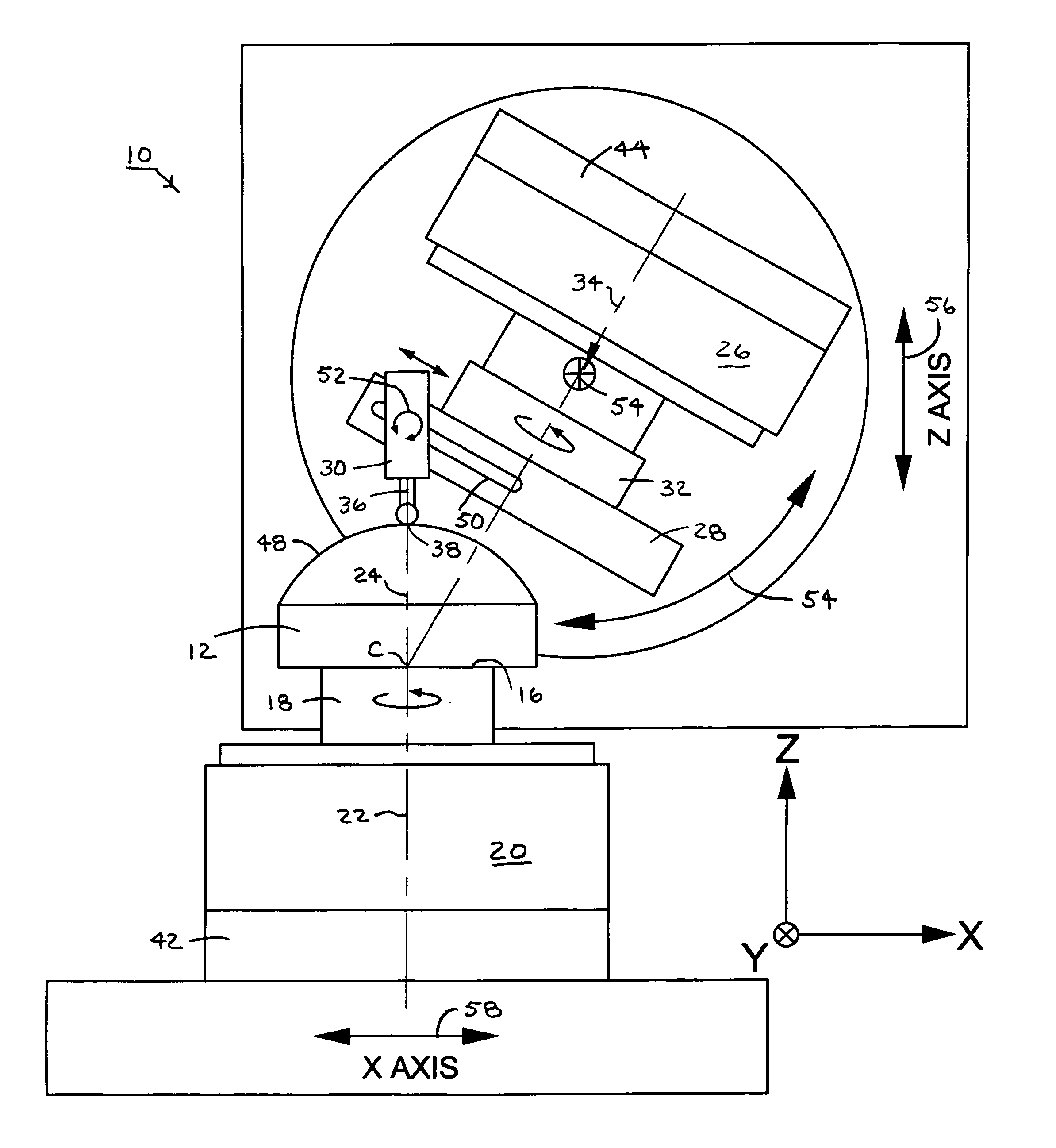
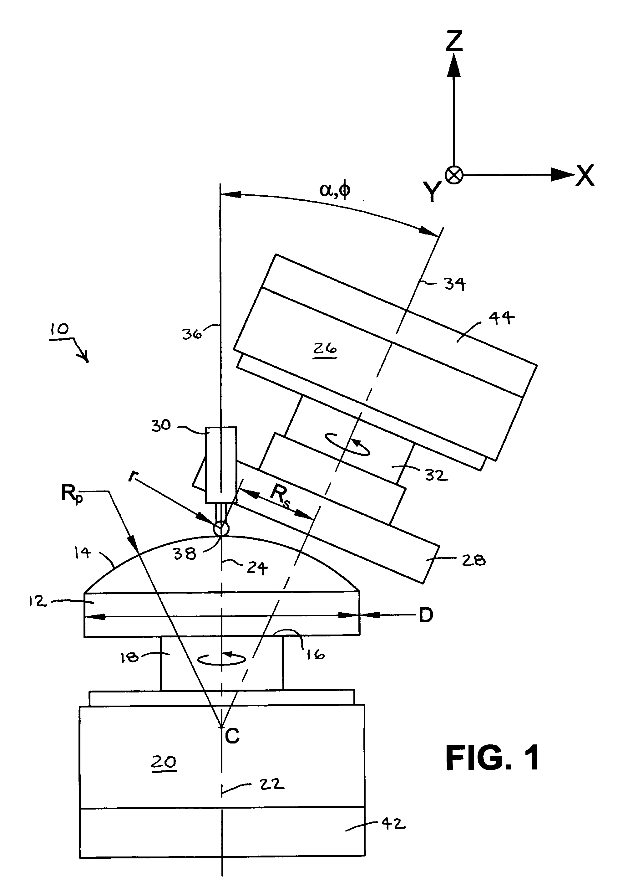
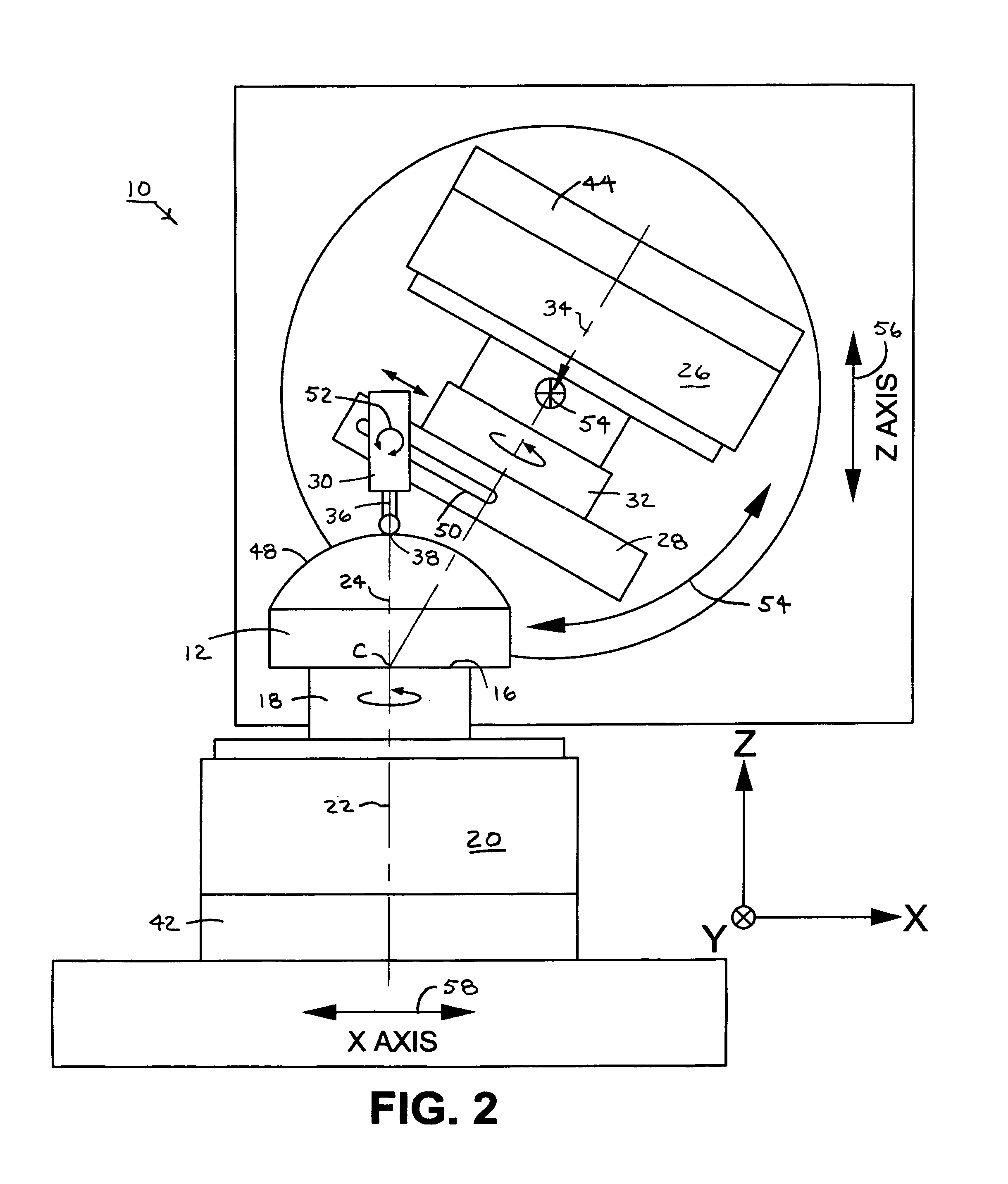
[0029]An exemplary instrument 10 for practicing the invention is shown in the drawing figures in various configurations and operating modes for measuring a range of spherical and aspherical optical surfaces. In FIG. 1, an optical element 12 having a convex optical test surface 14 is mounted on a fixture 16 at one end of a work spindle 18. The work spindle 18 is a part of a rotary drive 20 for rotating the optical element 12 around a rotational axis 22. The optical test surface 14 is mounted so that its center of curvature C lies along the rotational axis 22 and its nominal axis of symmetry 24 is coincident with the rotational axis 22.

[0030]The fixture 16 mounting the test surface 14 is preferably a chuck such as a vacuum or mechanical chuck that permits of centration and angular orientation adjustments of the optical element 12 with respect to the rotational axis 22 of the work spindle 18. In addition, the optical element 12 is preferably rotatable within the fixture 16 to permit th...


PUM


Abstract

Rotational motions between a displacement-measuring probe and an optical test surface define a spherical or near spherical datum surface against which measurements of the probe are taken. The probe has a measurement axis that is maintained substantially normal to the optical test surface during the course of measurement.

Description

BACKGROUND OF THE INVENTION[0001]1. Field of the Invention[0002]Within the field of metrology, the invention contemplates the measurement of spherical and near-spherical optical surfaces with surface scanning based instruments.[0003]2. Description of Related Art[0004]The manufacture of precision optical surfaces requires high accuracy measurements of surface form. Generally, both reflective and refractive precision optical surfaces have a spherical form. However, many modern optical systems such as those used for micro-lithography applications include aspheric optical surfaces that depart somewhat from the spherical form to provide higher order optical manipulations.[0005]A number of systems have been developed for measuring such near-spherical optical surfaces to required precision. These include both optical and non-optical systems. The optical systems typically use interferometric techniques, which include comparing a reference wavefront having the nominal shape of an optical tes...

Claims


Application Information

Patent Timeline
Patent Type & Authority Patents(United States)
IPC IPC(8): G01B5/20G01B5/213G01B7/28G01B7/293G01B11/24G01B11/255G01B21/04G01B21/20G01M11/00
CPCG01B5/213G01B21/045
Inventor BADAMI, VIVEK G.BRUNING, JOHN H.
Owner CORNING INC
Why Eureka
Try Eureka