Device mounting apparatus

a technology for mounting devices and speakers, which is applied in the direction of mechanical devices, other domestic objects, machine supports, etc., can solve the problems of a single human operator's risky and troublesome operation, speaker unit falling, and speaker unit mounting operation using the speaker device mounting apparatus disclosed in the relevant patent literature, etc., to achieve accurate positioning at a desired position and facilitate orientation

Inactive Publication Date: 2013-12-12
YAMAHA CORP
View PDF5 Cites 24 Cited by
  • Summary
  • Abstract
  • Description
  • Claims
  • Application Information

AI Technical Summary

Benefits of technology

[0006]In view of the foregoing prior art problems, it is an object of the present invention to provide an improved device mounting apparatus which, when a device, such as a speaker, is to be mounted to a mounting surface of a ceiling, side wall or the like, or after the mounting, allows the device to be accurately positioned at a desired position and orientation with ease and in safety.
[0009]By the provision of the positioning mechanism where the engaging section is brought into meshing engagement with the engaged section by the dead weights of the first member and the device, the present invention allows a human operator to appropriately position the first member relative to the second member, because relative movement of the first member relative to the second movement is prevented when the engaging section is in the engagement with the engaged section in the positioning mechanism. Thus, in positioning the device, the human operator can readily perform the speaker unit positioning operation with a high accuracy and in safety by merely engaging the engaging section with the engaged section external using the dead weight of the device. As a result, the human operator can perform, with ease and in safety, the speaker unit positioning operation when the speaker unit is to be mounted to the mounting part (mounting surface), such as a ceiling or side wall, or positioning adjustment operation after the mounting to the mounting part.
[0011]By the provision of the positioning mechanism which positions the device using the dead weight of the device, the present invention allows positioning, about the shaft, of the first member and the device to be performed with ease and in safety. Thus, the present invention allows the orientation, in the rotational direction, of the device to be adjusted to any desired orientation with ease.
[0013]When a rotational orientation, about the shaft section, of the devices is to be determined at the time of positioning of the device, the present invention allows the device to be positioned in a desired orientation with a high accuracy. Further, with the positioning mechanism comprising the externally toothed engagement member and the internally toothed engagement member meshingly engaging with each other along their radially outer and inner peripheral surfaces, the present invention can minimize the possibility of the meshing engagement between the externally and internally toothed engagement members in the positioning mechanism being accidentally canceled. Namely, because the shaft section is inserted in the insertion section, the first member and the second member are not movable relative to each other in the radial direction although the first member and the second member are movable relative to each other in the axial direction. Therefore, if there is employed a construction where the engaging section and the engaged section of the positioning mechanism engage with each other in the axial direction, the engagement between the engaging section and the engaged section may be accidentally canceled easily as the first member moves in the axial direction. By contrast, in the present where the engaging section and the engaged section mesh with each other along their radially outer and inner peripheral surfaces, i.e. mesh with each other in a direction perpendicular to the axial direction of the shaft section fittingly inserted in the insertion section, there is no possibility of the engagement between the engaging section and the engaged section being accidentally canceled. As a result, the present invention can effectively prevent positional deviation of the device after the positioning of the device.
[0015]By the fastening member engaging with the larger-diameter portion of the shaft section adjoining the narrowed portion, the present invention can prevent the shaft section from accidentally coming out of the insertion section. In this way, the present invention can prevent the first and second members from being accidentally disassembled from each other, and thus, it can prevent the device, mounted on the mounting surface like a side wall via the inventive device mounting apparatus comprising the first and second members, from accidentally falling down from the mounting surface.
[0017]Thus, even when, for positioning the first member about the shaft section, the first member is moved relative to the second member in the axial direction to cancel the meshing engagement between the engaging and engaged section, the present invention can keep the shaft section in a state capable of being prevented from coming out of the insertion section, by the fastening member screw engaging with the narrowed portion and particularly with an end of the narrowed portion, more specifically the larger-diameter portion adjoining the narrowed portion. In this way, when the first member and the device are to be positioned relative to the second member, the present invention can avoid the risk or possibility of the first member and the second member from being accidentally disassembled from each other so that the first member and the device fall down from the mounting part.

Problems solved by technology

However, with the speaker device mounting apparatus disclosed in the relevant patent literature, the position and angle (orientation) of the speaker-side mounting member relative to the bar-shaped section is not determined until the knob portion of the fastening screw is fully tightened.
Because such an operation is performed at a high position above the human operator's head near the ceiling of the room, it tends to become a very difficult operation.
Further, in case the human operator accidentally releases the hand, supporting the speaker unit, form the speaker unit during the aforementioned operation, the speaker unit may fall.
Therefore, the speaker unit mounting operation using the speaker device mounting apparatus disclosed in the relevant patent literature tends to be risky and troublesome for a single human operator to perform.
Therefore, the human operator cannot easily mount the speaker unit to a mounting surface with the speaker unit positioned at a desired position and at a desired orientation.
Besides, it is difficult to secure safety during the speaker unit mounting operation.

Method used


Image

  • Device mounting apparatus
  • Device mounting apparatus
  • Device mounting apparatus

Examples


Embodiment Construction

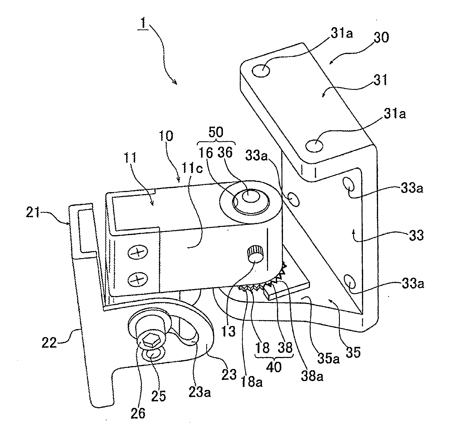
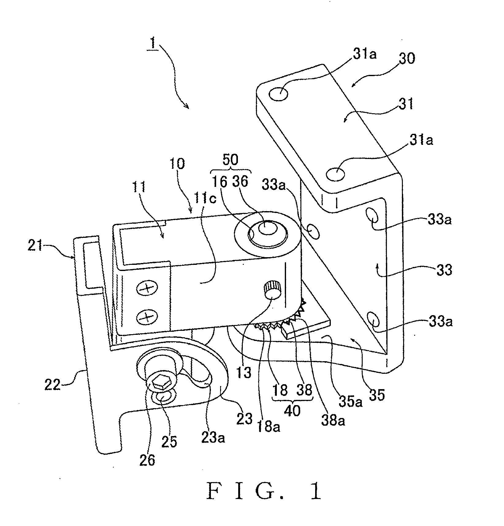
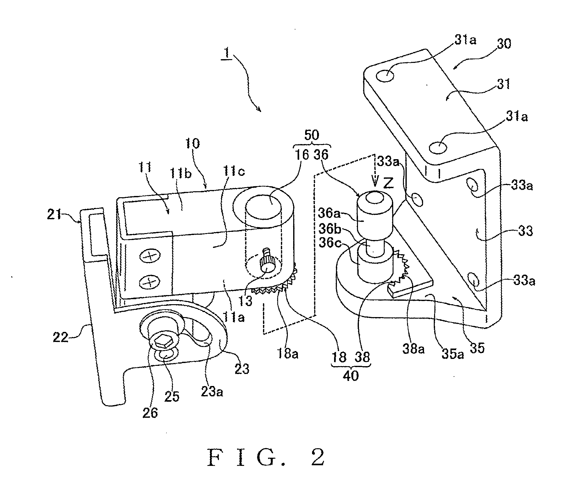
[0025]FIGS. 1 and 2 are perspective views showing a speaker mounting apparatus 1 according to a preferred embodiment of the present invention, of which FIG. 1 shows a later-described support member 10 and fixing plate 30 in an assembled state while FIG. 2 shows the support member 10 and fixing plate 30 in a disassembled state. Further, FIG. 3 is a partly sectional side view, taken along an X-X arrowed line of FIG. 4, showing the speaker mounting apparatus 1 with a speaker unit 60 mounted to a wall section 70. The speaker mounting apparatus 1 shown in these figures includes the support member 10 (i.e., a first member) adapted to be fixed to the speaker unit 60, and the fixing plate 30 (i.e., a second member) adapted to be fixed to a mounting surface (i.e., a mounting part) of the wall section 70, such as a ceiling 70a and side wall 70b of a room.

[0026]The fixing plate 30, which is a member formed by bending a metal plate into a generally U sectional shape, integrally has an upper pla...


PUM


Abstract

A speaker mounting apparatus for mounting a mounting part includes: a support member to be fixed to the speaker unit; a fixing plate to be fixed to the mounting part; and a positioning mechanism including an externally toothed engagement member provided on the support member and an internally toothed engagement member provided on the fixing plate. The externally toothed engagement member is brought into the internally toothed engagement member by the dead weight of the support member or the speaker unit fixed to the support member. Thus, movement of the support member relative to the fixing plate is prevented so that the support member is positioned in a peripheral direction (rotational direction) relative to the fixing plate.

Description

BACKGROUND[0001]The present invention relates to device mounting apparatus for mounting a device, such as a speaker unit, to a mounting surface of a wall section, pillar or the like.[0002]Among examples of the conventionally-known device mounting apparatus for mounting various pieces of equipment or devices, such as speaker units and illuminating devices, to mounting surfaces like ceilings, side walls and pillars of rooms is a speaker device mounting apparatus disclosed in Japanese Patent Application Laid-open Publication No. 2001-317508 (hereinafter referred to as “the relevant patent literature”). The speaker device mounting apparatus disclosed in the relevant patent literature is capable of adjusting vertical and horizontal orientations (mounted angles) of a speaker unit when the speaker unit is to be mounted to a wall, pillar or the like.[0003]According to the disclosure of the relevant patent literature, the speaker unit is fixed to a speaker-side mounting member in advance, bu...

Claims


Application Information

Patent Timeline
Patent Type & Authority Applications(United States)
IPC IPC(8): F16M13/02
CPCF16M13/022F16M11/10F16M11/2014F16M13/02H04R1/026
Inventor YOSHIDA, MASAOATSUMI, KAZUYA
Owner YAMAHA CORP
Why Eureka
Try Eureka