System element for the transporting and positioning of tools

Inactive Publication Date: 2007-08-30
AIRBUS OPERATIONS GMBH
View PDF1 Cites 3 Cited by
  • Summary
  • Abstract
  • Description
  • Claims
  • Application Information

AI Technical Summary

Benefits of technology

[0006] Among other things, it may be an object to create an option for safely transportin

Problems solved by technology

This approach may be associated with some problems of implementing locomotion.
Furthermor

Method used


Image

  • System element for the transporting and positioning of tools
  • System element for the transporting and positioning of tools
  • System element for the transporting and positioning of tools

Examples


Embodiment Construction

[0031] The examples described and drawings rendered are illustrative and are not to be read as limiting the scope of the invention as it is defined by the appended claims.

[0032] Below, the same reference characters are used for identical components in the different views of the figures. The illustrations in the figures are diagrammatic and not to scale.

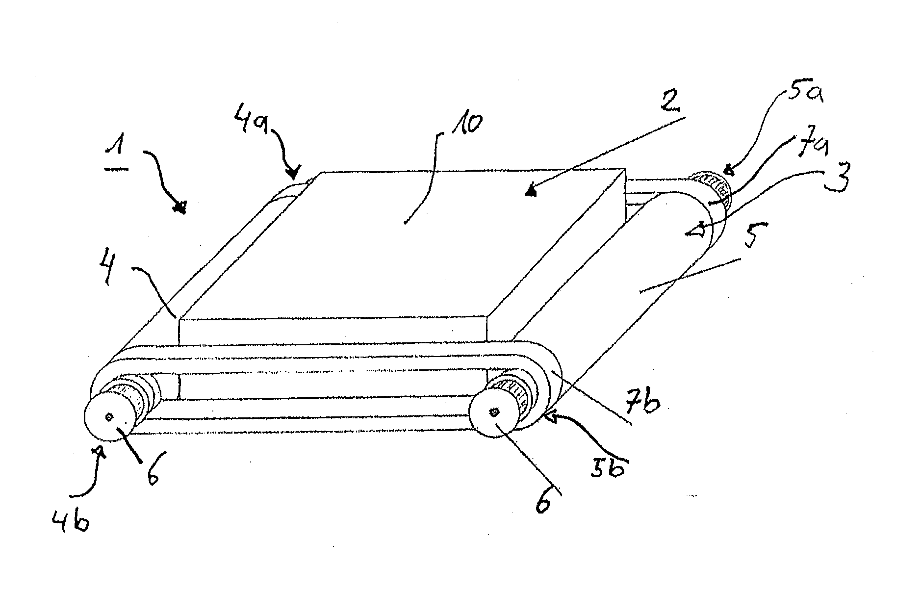
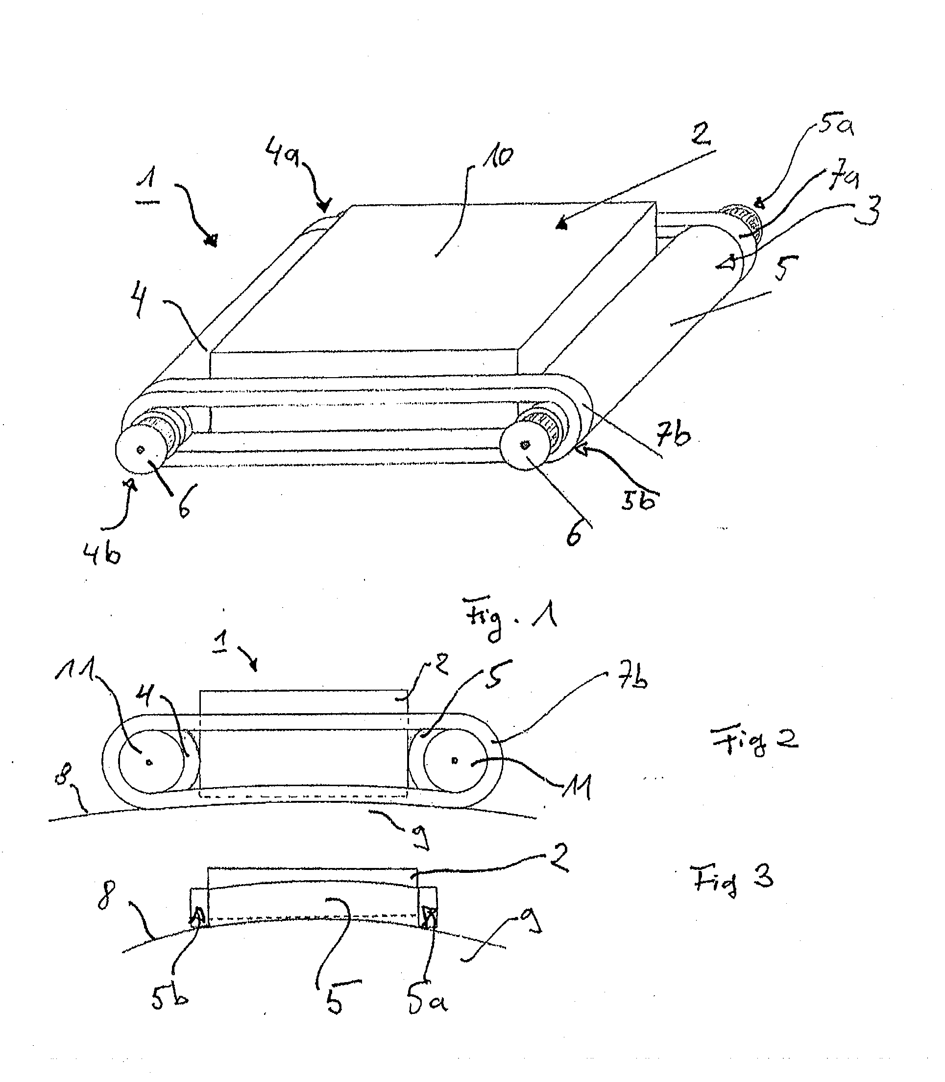
[0033] In FIG. 1, the system element 1 comprises a suction chamber 2 which is used for generating a suction stream and which is a generally known component, known by a person of ordinary skill in the art. The system element 1 further comprises a transport device 3 that encloses lateral walls of the suction chamber 2.

[0034] As shown in FIG. 1, the transport device 3 comprises a first roller 4 and a second roller 5, where the rollers are arranged at opposite lateral surfaces of the suction chamber 2 and contact the respective lateral surface.

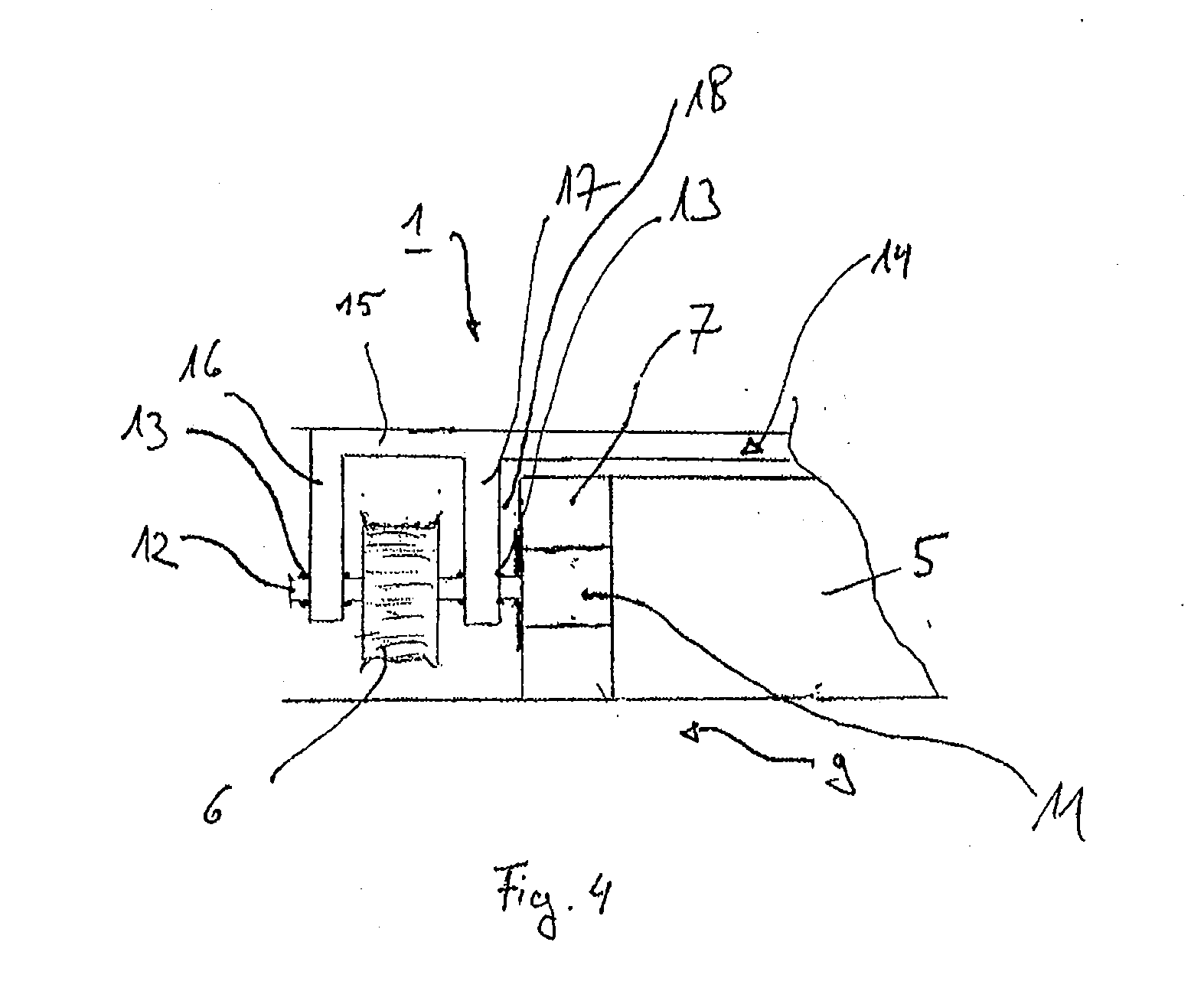
[0035] According to the embodiment, pulleys 6 for driving the rollers 4, 5 and thus for driv...


PUM


Abstract

A system element for the transporting and positioning of a tool on a surface of a workpiece, includes at least one suction device that generates a suction stream, and a transport device that is arranged around the suction device, and includes: at least two rollers that are rotatably supported on the suction device, connection elements that interconnect respective end regions of various rollers, and the rollers and the connection elements are elastically deformable, and when there is a suction stream, the system element substantially conforms with the surface of the workpiece.

Description

REFERENCE TO RELATED APPLICATIONS [0001] This application claims the benefit of the filing date of German Patent Application No. 10 2006 005 524.1 filed Feb. 7, 2006 and of U.S. Provisional Patent Application No. 60 / 771,196 filed Feb. 7, 2006, the disclosures of which applications are hereby incorporated herein by reference.FIELD OF THE INVENTION [0002] The field relates to a system element for the transporting and positioning of a tool on a surface of a workpiece. BACKGROUND OF THE INVENTION [0003] In order to use robots for machining large workpieces, it may be economical to rigidly position the workpiece and to let the robot move to the position where machining is to occur. If the dimension of the robot is to be kept small, the robot may be moved to a suitable position. If the workpiece is sufficiently stable, there may be no need to use external devices for leading the robot into position, for example, for scaffolds, provided the technical task of moving over the workpiece is so...

Claims


Application Information

Patent Timeline
IPC IPC(8): B65H3/08
CPCB62D55/075B62D57/00B62D55/265
Inventor KOTT, HORSTBERGUNDE, MANFRED
Owner AIRBUS OPERATIONS GMBH
Why Eureka
Try Eureka