
Adjustable gripper pads

a technology of adjustable gripper and gripper head, which is applied in the direction of gripping head, pliers, thin material handling, etc., can solve the problems of pad loss, time-consuming replacement of pads, and pads that are not in use that require storage space,

Active Publication Date: 2007-08-30
SYRON ENG & MFG
View PDF18 Cites 35 Cited by
  • Summary
  • Abstract
  • Description
  • Claims
  • Application Information

AI Technical Summary

Problems solved by technology

Although conventional gripper pads are effective for clamping and transferring work pieces or other objects, using replaceable pads complicates use of the handling equipment, and pad replacement is time-consuming.
Additionally, pads that are not in use require storage space and may become lost.

Method used


Image

  • Adjustable gripper pads
  • Adjustable gripper pads
  • Adjustable gripper pads

Examples


Embodiment Construction

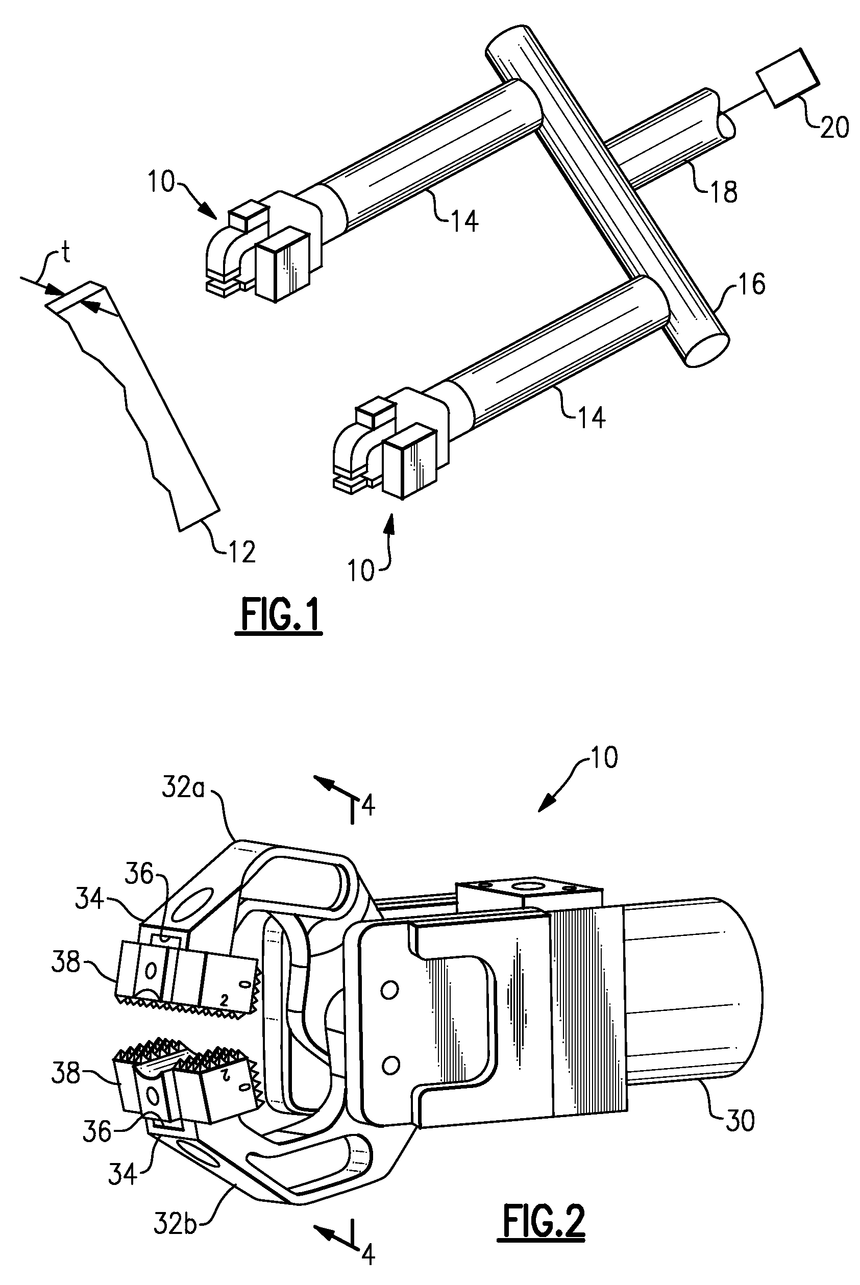
[0020]FIG. 1 illustrates selected portions of several gripper assemblies 10 used in an example industrial setting to grip and move a work piece 12 (shown schematically). The gripper assemblies 10 may be used in a variety of different configurations and different settings from that shown. In the illustrated example, the gripper assemblies 10 are coupled to extended arms 14, which are each secured to a rail 16. An adapter arm 18 is secured to the rail 16. An automated machine 20, such as a robot, moves the adapter arm 18, the extended arms 14, and the gripper assemblies 10 to desired positions to retrieve and deposit the work pieces 12, such as between work stations.

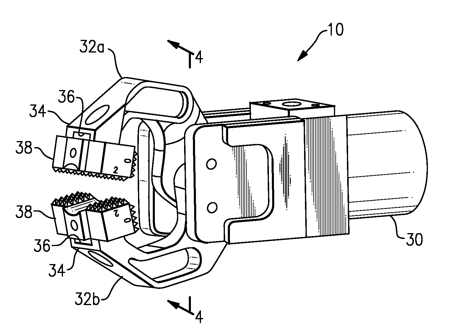
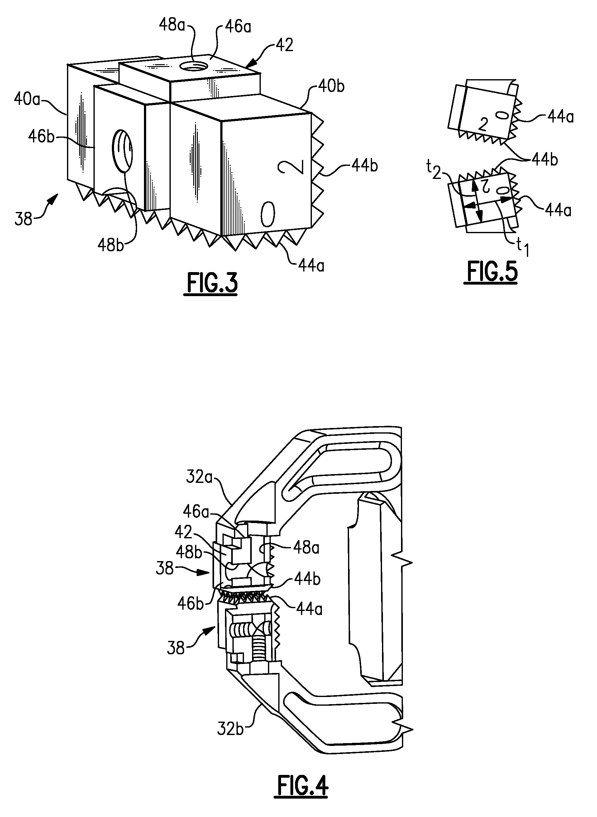
[0021]Referring to FIG. 2, each of the gripper assemblies 10 includes an actuator 30, such as a pneumatic or hydraulic actuator. It is to be understood that other types of actuators may also be used. The actuator selectively reciprocates a piston (not shown) to open or close gripper jaws 32a and 32b in a known manner. In t...


PUM


Abstract

A gripper tip for use with a gripper assembly includes a first gripping surface located at least partially within a first plane and a second gripping surface located at least partially within a second plane that is transverse to the first plane. The first gripping surface includes a first gripping height relative to a first attachment portion associated with the first gripping surface. The second gripping includes a second gripping height relative to a second attachment portion associated with the second gripping surface, and the second gripping height is greater than the first gripping height.

Description

RELATED APPLICATIONS[0001]The application claims priority to U.S. Provisional Application No. 60 / 776,452, which was filed on Feb. 24, 2006.BACKGROUND OF THE INVENTION[0002]This invention generally relates to automated handling equipment. More particularly, this invention relates to an actuated gripper device.[0003]Automated handling equipment is typically employed in industrial settings for transferring work pieces between work stations. Typically, the equipment includes a gripper that clamps the work pieces while moving them between the stations. Conventional grippers include an actuator that moves one or more gripper jaws between open and closed jaw positions.[0004]Typically, the jaws include removable gripper tips or pads that include teeth to facilitate gripping of the work pieces. The pads are removable and replaceable with different pads to provide different teeth or to accommodate different sizes or shapes of work pieces. For example, the pad thickness corresponds to the dist...

Claims


Application Information

Patent Timeline
IPC IPC(8): B25J15/02
CPCB25B5/061B25J15/0475B25B7/04B25B5/163Y10S294/902
Inventor KEY, TIMOTHY JOHNCARROLL, SCOTT RICHARDFILIPIAK, MICHAEL ARTHUR
Owner SYRON ENG & MFG
Features
  • Generate Ideas
  • Intellectual Property
  • Life Sciences
  • Materials
  • Tech Scout
  • Unparalleled Data Quality
  • Higher Quality Content
  • 60% Fewer Hallucinations
Learn More