Workpiece cloth positioning guide device for sewing machine

a positioning guide and sewing machine technology, applied in the direction of workfeeding means, sewing apparatus, textiles and paper, etc., can solve the problems of difficulty in forming stitches, difficulty in positioning the edge and difficulty for the operator to get the position of the workpiece cloth and the previously formed stitches

Active Publication Date: 2007-09-06
BROTHER KOGYO KK
View PDF6 Cites 21 Cited by
  • Summary
  • Abstract
  • Description
  • Claims
  • Application Information

AI Technical Summary

Benefits of technology

[0011]Therefore, an object of the disclosure is to provide a workpiece cloth positioning guide device for a sewing machine, which projects onto an upper side of the workpiece cloth a sewing reference mark including a circle with a center corresponding with a needle drop point and positioning the workpiece cloth relative to the sewing reference mark, thereby being capable of forming stitches readily and reliably so that the stitches are spaced away by a predetermined stitch interval from the edge of each of workpiece cloths having various shapes including a curved one or from the stitches previously formed on the workpiece cloth, the workpiece cloth positioning guide device being capable of varying the stitch interval to a desired interval and readily carrying out the variation of the stitch interval.

Problems solved by technology

Moreover, the operator has difficulty in getting positions of the edge of the workpiece cloth and the previously formed stitches relative to the presser foot.
Accordingly, it becomes difficult to position the edge of the workpiece cloth and the previously formed stitches accurately relative to the presser foot and further, to feed the workpiece cloth so that the edge of the workpiece cloth and the previously formed stitches are maintained at the positions.
Thus, it is difficult for the operator to form stitches with a predetermined stitch interval relative to the edge of the workpiece cloth or previously formed stitches.
Furthermore, since the stitch interval depends upon the size of the presser foot, the stitch interval cannot be changed unless the presser foot is changed to another with a different size.
However, changing the presser foot is extremely troublesome for the operator, and providing a plurality of presser feet results in cost disadvantage.
Furthermore, the number of presser feet to be provided has a definite limit.
As a result, changing the stitch interval also has a definite limit, and the stitch interval cannot be changed to a desired value in many cases.
As a result, the sewing machine disclosed by Japanese Patent No. 277596 has a difficulty in forming stitches with a predetermined stitch interval being provided relative to the edge of the workpiece cloth including a curved one as in the case where a presser foot is used in the apparatus shown in FIG. 20.

Method used


Image

  • Workpiece cloth positioning guide device for sewing machine
  • Workpiece cloth positioning guide device for sewing machine
  • Workpiece cloth positioning guide device for sewing machine

Examples


Embodiment Construction

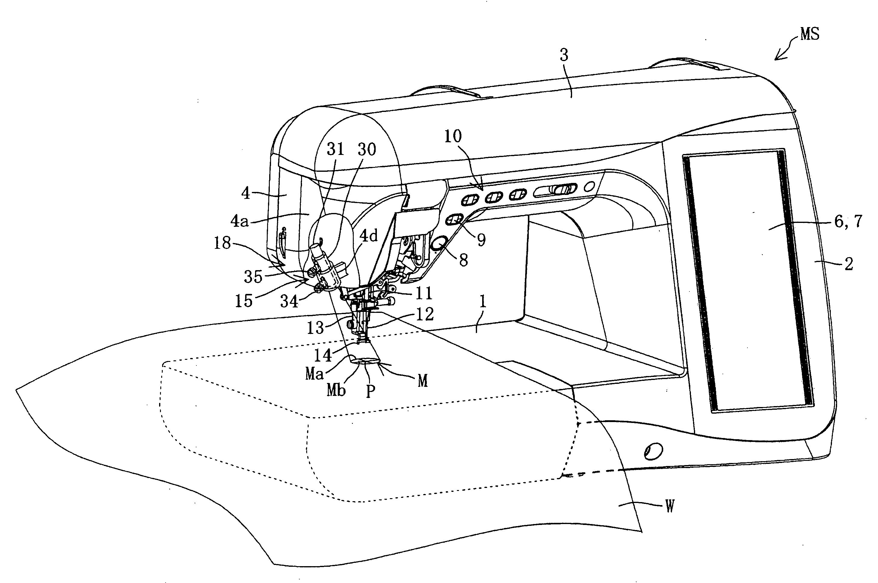
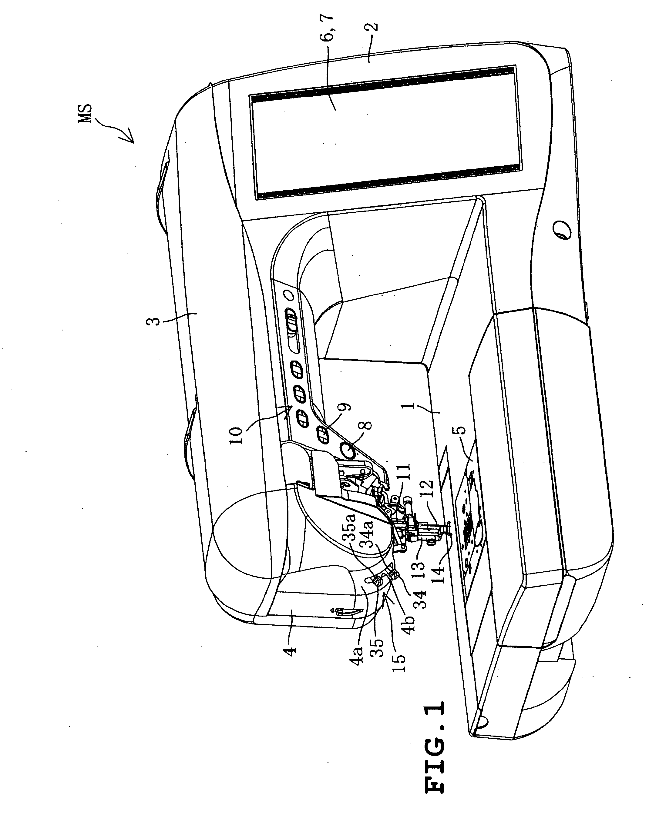
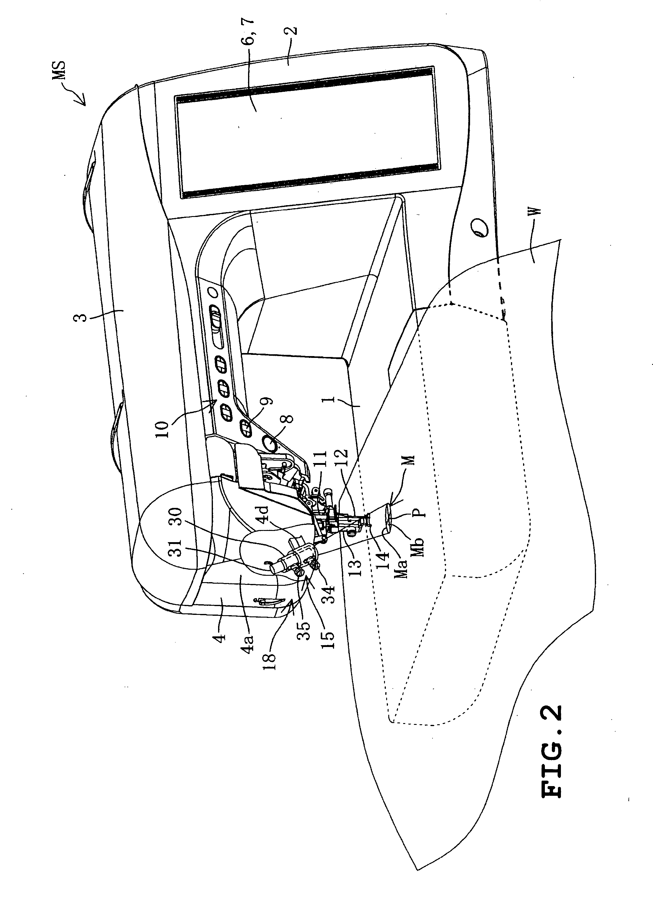
[0037]A first embodiment of the present disclosure will be described with reference to FIGS. 1 to 12. Referring to FIGS. 1 and 2, a sewing machine MS includes a sewing bed 1, a sewing pillar 2 extending upward from a right part of the bed 1, a sewing arm 3 extending leftward from an upper end of the pillar 2 and a sewing head 4 mounted on a left end of the arm 3. The bed 1 has an upper side on which a needle plate 5 is mounted. The pillar 2 has a front on which a liquid crystal display 6 capable of performing color display is provided. The liquid crystal display 6 has a front on which a transparent touch panel 7 is provided. Various operation switches 10 including a start switch 8 and a projecting switch 9 are provided on fronts of the 7. arm 3 and head 4.

[0038]A sewing machine main shaft (not shown) is provided in the arm 3 so as to be driven by a sewing machine motor 17 (see FIG. 3). A needle bar 11 is attached to the head 4 so as to be swingable vertically. The needle bar 11 is d...


PUM


Abstract

A workpiece cloth positioning guide device for a sewing machine includes a projector which projects a sewing reference mark onto an upper side of workpiece cloth placed on a sewing bed of the sewing machine. The projector projects light emitted from the light source onto a needle drop reference point of the sewing needle of the sewing machine from obliquely above so that a sewing reference mark including a circle having a center at the needle drop reference point on the upper side of the workpiece cloth and the sewing reference mark guides the workpiece cloth when the workpiece cloth is positioned in sewing.

Description

CROSS-REFERENCE TO RELATED APPLICATIONS[0001]This application is based upon and claims the benefit of priority from the prior Japanese Patent Application No. 2006-57286 filed on Mar. 3, 2006, the entire contents of which are incorporated herein by reference.BACKGROUND[0002]1. Technical Field[0003]The present disclosure relates to a workpiece cloth positioning guide device for a sewing machine, which projects a sewing reference mark onto an upper surface of workpiece cloth placed on a sewing bed of a sewing machine thereby to guide the positioning of the workpiece cloth in a sewing operation.[0004]2. Description of the Related Art[0005]In sewing workpiece cloth by a sewing machine, stitches are sometimes formed with a predetermined distance from an edge of the workpiece cloth or stitches previously formed on the workpiece cloth. There has conventionally been provided a device comprising a generally rectangular presser foot 100 as shown in FIG. 20, for example. In sewing, an edge 101a...

Claims


Application Information

Patent Timeline
Patent Type & Authority Applications(United States)
IPC IPC(8): D05B79/00
CPCD05B19/12D05B79/00D05B35/12
Inventor YAMASAKI, HIROSHI
Owner BROTHER KOGYO KK
Why Eureka
Try Eureka