

Integrated LED Light Bars and Roof Structure for Trailers
- Summary
- Abstract
- Description
- Claims
- Application Information
AI Technical Summary
Problems solved by technology
Method used
Image

Examples
first embodiment
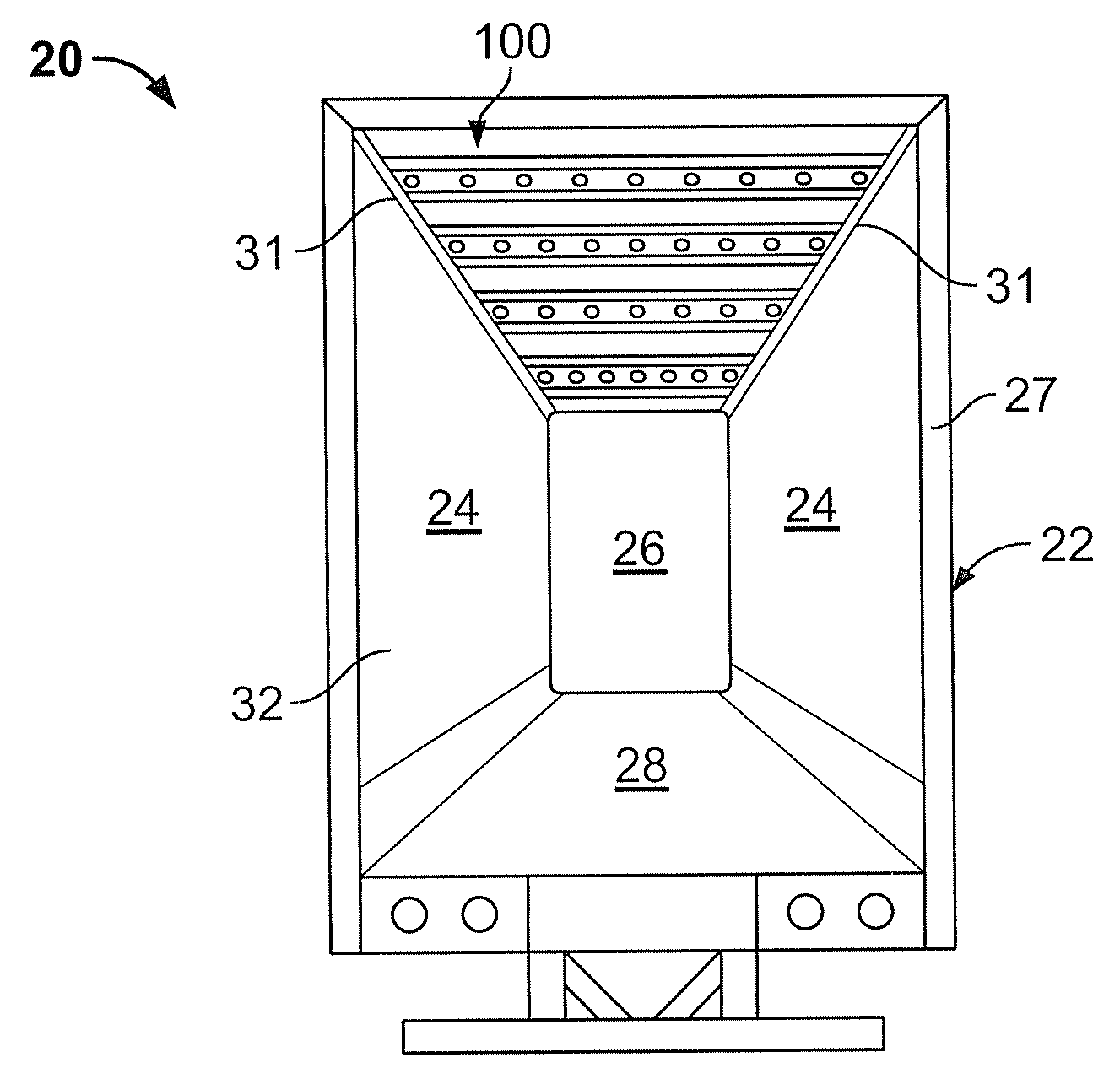
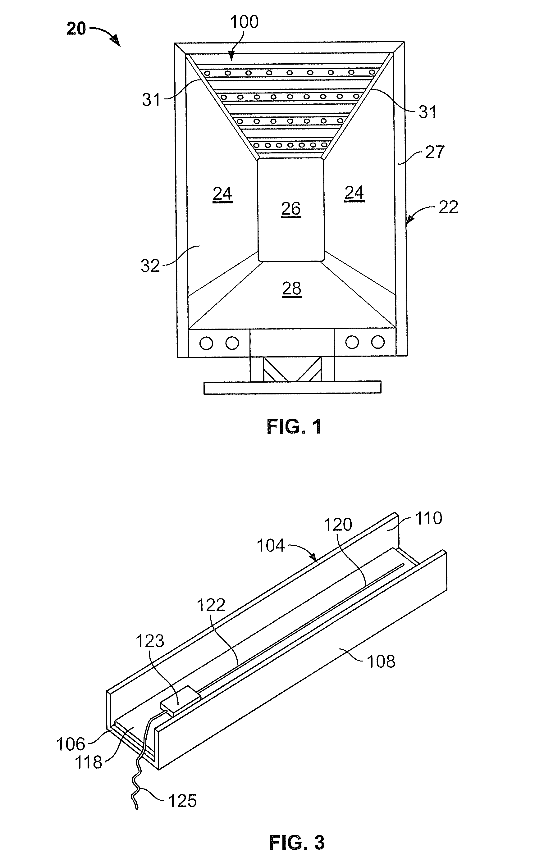
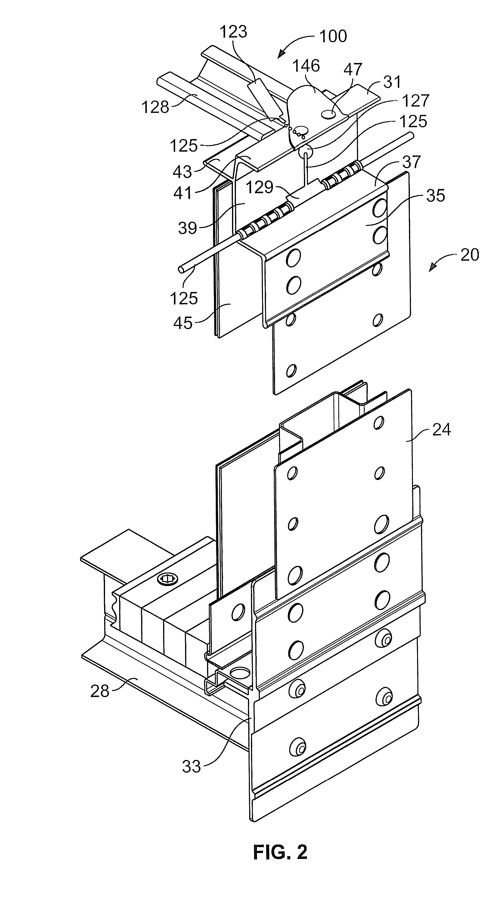
[0040]Attention is invited to FIGS. 2-10 which shows the specifics of the roof assembly 100 for a dry freight trailer 20. The roof assembly 100 is provided with a plurality of LED lights 102 for lighting an interior 32 of the trailer 22, which is defined between the sidewalls 24, the front wall 26, the rear doors, the roof assembly 100 and the floor assembly 28.
[0041]The roof assembly 100 includes a plurality of spaced apart roof bows 128, a LED light bar 126 provided in at least one of the roof bows 128, and a roof sheet 146. The roof bows 128 are secured to the top rail 31 by known means, such as rivets (not shown) extending through the roof bow 128 and the flange 43. The roof sheet 146 sits on top of the roof bows 128 and the fourth wall 41 of the top rail 31. The roof sheet 146 is secured to the top rails 31 by known means, such as rivets 47 extending through the roof sheet 146 and the fourth wall 41. The roof sheet 146 is secured to the roof bows 128 by known means, such as adh...
second embodiment
[0059]Attention is now invited to FIGS. 12-16 which shows the roof assembly 200. The roof assembly 200 is provided with a plurality of LED lights 202 for lighting an interior 32a of the trailer 22a, which is defined between the sidewalls 24a, the front wall 26a, the rear doors, the roof assembly 200 and the floor assembly 28a.
[0060]The roof assembly 200 includes a plurality of spaced apart roof bows 228, a LED light bar 226 provided in at least one of the roof bows 228, and a roof sheet 246. The roof sheet 246 sits underneath the roof bows 228 and the roof sheet 246 and roof bows 228 are secured to the top rails 31a. This structure is shown in co-pending U.S. application Ser. No. 11 / 563,796, filed on Nov. 28, 2006, claiming benefit of provisional application Ser. No. 60 / 748,726 filed on Dec. 8, 2005, which disclosure in its entirety is herein incorporated by reference.
[0061]Each LED light bar 226 is identical in configuration and construction to the LED light bars 126 utilized in t...
third embodiment
[0070]Attention is invited to FIGS. 17-22 which shows the specifics of the roof assembly 300. This roof assembly 300 is used in a trailer 20b, which may be a dry freight trailer or a refrigerated trailer. The roof assembly 300 is provided with a plurality of LED lights 302 for lighting an interior 32b of the trailer 20b, which is defined between the sidewalls 24b, the front wall 26b, the rear doors, the roof assembly 300 and the floor assembly 28b.
[0071]FIGS. 17 and 18 illustrate the trailer 20b having a roof assembly 300 which incorporates features of the present invention. The trailer 20b generally includes a body 22b formed from opposite sidewalls 24b, a front wall 26b, a front frame (not shown) to which the front wall 26b is attached, rear doors (not shown), a rear frame 27b, the roof assembly 300, and a floor assembly 28b. A landing gear (not shown) and an undercarriage (not shown) attached are attached to the floor assembly 28b by known means. The roof assembly 300 and an upp...
PUM
 Abstract
Description
Claims
Application Information