Ablation device and system for guiding ablation device into body

a technology of ablation device and body, which is applied in the field of treatment of tissue of patients with ablative energy, can solve the problems of increasing the vulnerability to thromboembolism, significant patient discomfort and even death, and varying levels of congestive heart failur

Inactive Publication Date: 2007-09-06
MEDTRONIC INC
View PDF99 Cites 196 Cited by
  • Summary
  • Abstract
  • Description
  • Claims
  • Application Information

AI Technical Summary

Benefits of technology

[0017] The present invention provides advantages over prior art devices and methods for ablating tissue. One advantage is that the flexible nature of the neck allows the ablation device to fit the anatomies of different patients. Another advantage is that using an ablation device with such a flexible neck can reduce the number of ports of entry into a body that need to be made to perform an ablation procedure, because more areas of the heart may be reached by the device using a single port. Yet another advantage of the present invention is, because the clamping jaws may be in a parallel configuration in a closed position and because the neck is flexible, the jaw end of the device may fit easily through small ports used in minimally invasive procedures. A further advantage of the present invention is the flexibility of the neck allows a surgeon to use a variety of approaches to an ablation procedure. An additional advantage is that the clamping jaws are a floating jaw design, which can function with a variety of tissue configurations or thicknesses. A still further advantage is that ablative energy may only be applied when the clamping jaws are in a closed position and the lockout mechanism is deactivated by the user, which avoids applying ablative energy to undesired tissue while maneuvering the device into a body. Further, the controls for the device are conveniently located on the handle, which is being held and controlled by the user. An advantage of the system of the present invention is the option for the ablation device to be able to be rapidly associated and disassociated with a guide wire system to assist in placement of the ablation device.
[0018] A first embodiment of the present invention is a device for ablating tissue at a desired location in a body, the device comprising: a pair of floating jaws moveable between a spaced apart open position and a closed position, the pair of jaws comprising at least one ablating element for ablating tissue located between the jaws; a handle comprising controls for remotely controlling the movement of the jaws and the at least one ablative element; and a flexible neck connecting the jaws and handle, wherein the neck is flexible so as to permit the jaws to be maneuverable in the body with respect to the handle. The open position of the jaws in the device may be scissor-like in configuration while that in the closed position may be parallel in configuration. The ablating element of the device may comprise a fluid assisted electrode assembly. The controls of the handle may comprise a lever that when moved causes the jaws to move between the open position and the closed position. The controls for the at least one ablating element may comprise a trigger that activates an ablative power source. The controls of the handle may comprise a lock for locking the jaws in the closed position. The controls of the handle may comprise an overdrive mechanism for limiting closure of the jaws. The overdrive mechanism may comprise a clutch assembly.
[0019] A second embodiment is a device for ablating tissue, the device comprising: a pair of floating jaws moveable between a spaced apart open position and a closed position, the pair of jaws comprising at least one ablating element for ablating tissue located between the jaws, wherein the open position of the jaws is scissor-like in configuration and the closed position is parallel in configuration; a handle comprising controls for remotely controlling the movement of the jaws and the at least one ablative element; and a neck connecting the jaws and handle.
[0020] A third embodiment of the present invention is a system for guiding an ablation device to a desired location in a body, the system comprising: an ablation device having a pair of jaws comprising at least one ablating element for ablating tissue located between the jaws; and means for guiding the ablation device to the desired location that may be attached and reattached to the ablation device. The ablation device of the system may comprise: a pair of floating jaws moveable between a spaced apart open position and a closed position, the pair of jaws comprising at least one ablating element for ablating tissue located between the jaws; a handle comprising controls for remotely controlling the movement of the jaws and the at least one ablative element; and a flexible neck connecting the jaws and handle, wherein the neck is flexible so as to permit the jaws to be maneuverable in the body with respect to the handle. The means for guiding the ablation device may comprise at least one guide member, the guide member comprising a tube connected to an attachment means that cooperates with an attachment means on the jaws of the ablation device.

Problems solved by technology

Arrhythmia can result in significant patient discomfort and even death because of a number of associated problems, including the following: (1) an irregular heart rate, which causes a patient discomfort and anxiety; (2) loss of synchronous atrioventricular contractions, which compromises cardiac hemodynamics resulting in varying levels of congestive heart failure; and (3) stasis of blood flow, which increases vulnerability to thromboembolism.
It is sometimes difficult to isolate a specific pathological cause of the arrhythmia although it is believed that the principal mechanism is one or a multitude of stray circuits within the left and / or right atrium.
These circuits or stray electrical signals are believed to interfere with the normal electrochemical signals passing from the SA node to the AV node and into the ventricles.
While arrhythmic drugs may be the treatment of choice for many patients, these drugs may only mask the symptoms and do not cure the underlying cause.
However, the procedure is technically difficult.
Precise positioning of the ablation device is especially difficult because of the physiology of the heart, particularly as such recently developed procedures generally occur off-pump.
Suturing near a beating heart involves risk of negative consequences.
Another challenge to placing ablation devices within or near the heart is that the anatomy of individual patients may differ, requiring different entry points or ports to gain access to the heart.
Some current ablation devices include ablating elements connected to rigid elements that are difficult to position within a patient.
Manipulation of such rigid elements is problematic and can lead to tissue damage.
Such separate controls may cause the surgeon to direct attention away from the patient.
In addition, such separate controls may be out of reach of the surgeon, which means another person may need to manipulate the controls.
These issues relating to the proximity of the controls to the surgeon can result in erroneous application of ablative energy at undesired locations in a patient or at undesired times during an ablation procedure.
Additionally, with regard to some minimally invasive procedures in particular, such remote controls or switches may be required to be moved around the operating room as the surgeon moves around to access different parts of the body, which is not desired.
Even if controls for activating the ablative energy source are located on a handle of the ablation device that is in the hands of the surgeon, during manipulation and placement of the device within a body, the ablative energy controls (e.g., trigger) can be accidentally activated when not desired.

Method used


Image

  • Ablation device and system for guiding ablation device into body
  • Ablation device and system for guiding ablation device into body
  • Ablation device and system for guiding ablation device into body

Examples


Embodiment Construction

[0086] In the following detailed description of the preferred embodiments, reference is made to the accompanying figures which form a part hereof, and in which is shown by way of illustration specific embodiments in which the invention may be practiced. It is to be understood that other embodiments may be utilized and structural or logical changes may be made without departing from the scope of the present invention. The following detailed description, therefore, is not to be taken in a limiting sense, and the scope of the present invention is defined by the appended claims.

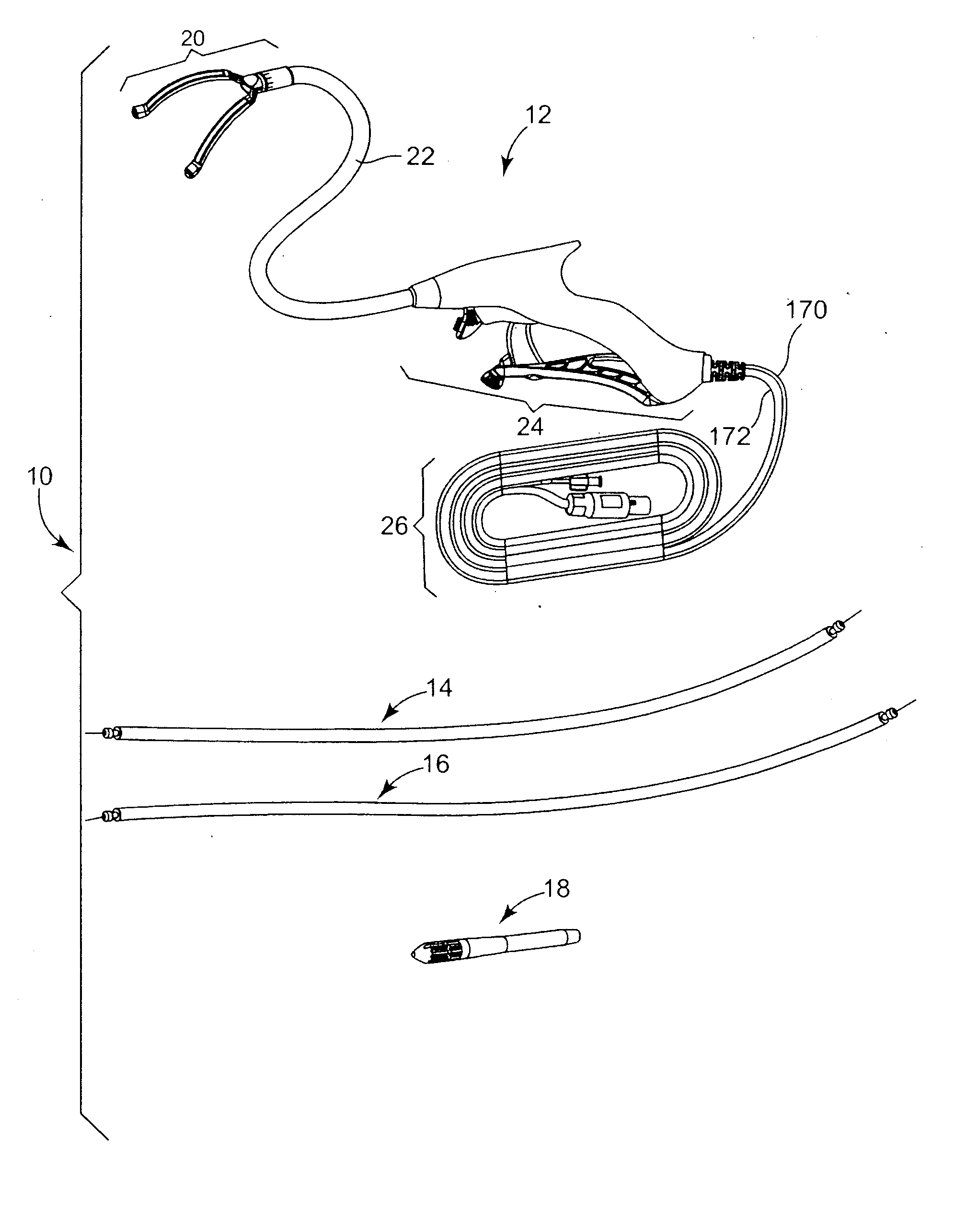
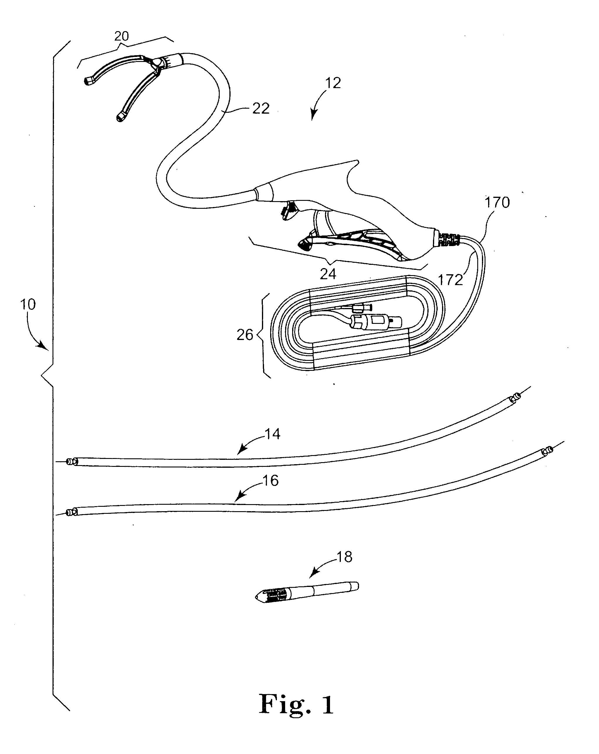
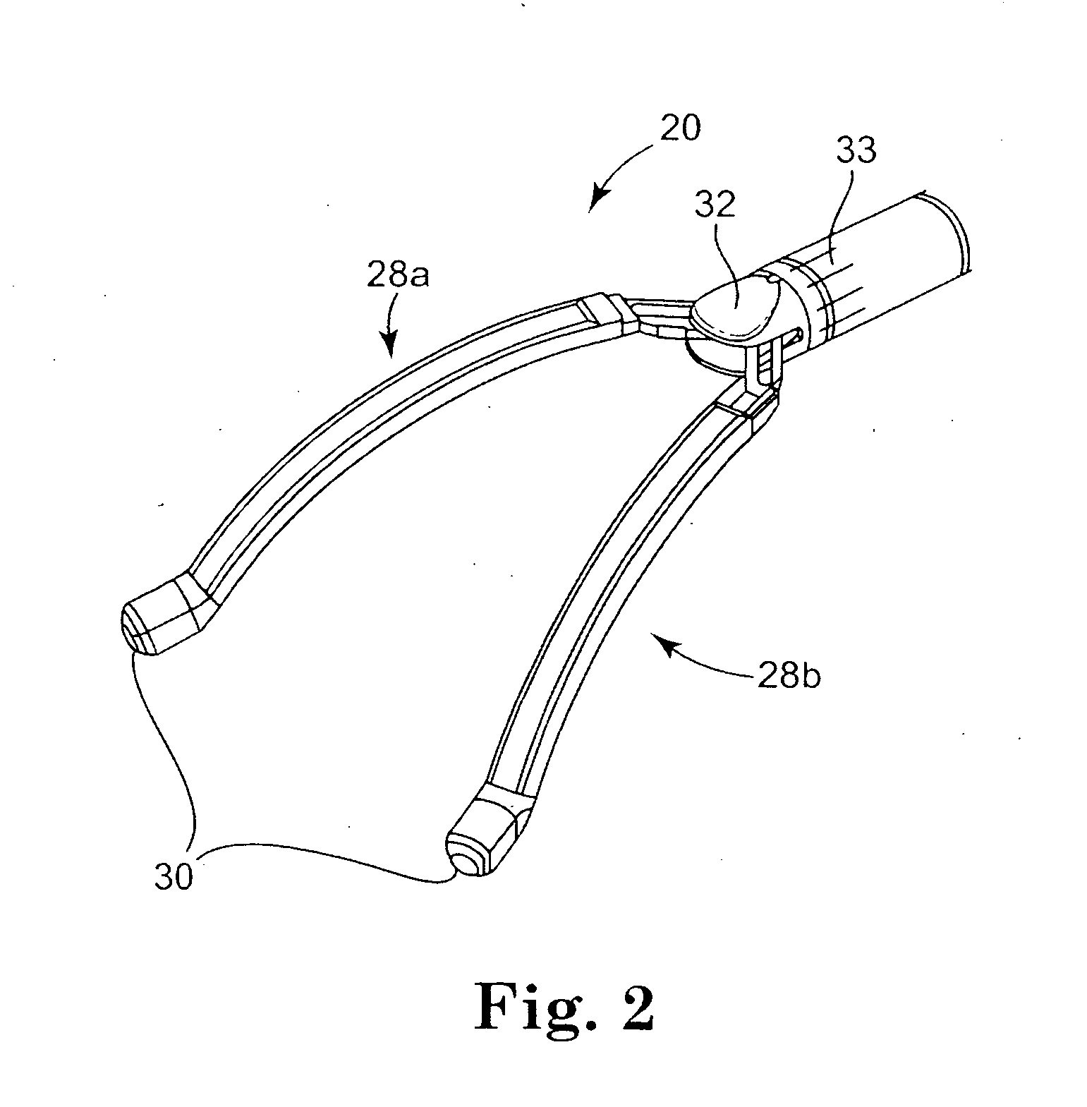
[0087] With reference to the accompanying figures, wherein like components are labeled with like numerals throughout the several figures, ablation devices, ablation systems, and methods of use thereof are disclosed, taught and suggested by the multiple embodiments for the purpose of ablation of tissue in a subject body. It is understood that any of the ablation devices, systems and methods, in accordance with th...


PUM


Abstract

A device for ablating tissue at a desired location in a body, the device comprising: a pair of floating jaws moveable between a spaced apart open position and a closed position, the pair of jaws comprising at least one ablating element for ablating tissue located between the jaws; a handle comprising controls for remotely controlling the movement of the jaws and the at least one ablative element; and a flexible neck connecting the jaws and handle, wherein the neck is flexible so as to permit the jaws to be maneuverable in the body with respect to the handle. A system for guiding an ablation device to a desired location in a body.

Description

CROSS REFERENCE TO RELATED APPLICATIONS [0001] This application claims the benefit of U.S. Provisional Application having Ser. No. 60 / 762,699, filed Jan. 27, 2006, entitled “ABLATION DEVICE AND METHOD,” which application is incorporated herein by reference in its entirety. [0002] This application also incorporates by reference in their entirety the following co-pending U.S. Patent Applications: application having Ser. No. ______, filed on the same day as the present application, entitled “METHODS OF USING ABLATION DEVICE AND OF GUIDING ABLATION DEVICE INTO BODY” and having Attorney Docket No. MT10053 / US (P-24242.02); and, application having Serial No. ______, filed on the same day as the present application, entitled “ABLATION DEVICE WITH LOCKOUT FEATURE” and having Attorney Docket No. MTI0054 / US (P-24242.03).FIELD OF THE INVENTION [0003] The present invention relates generally to the treatment of tissue of a patient with ablative energy and, more particularly, to the an ablation de...

Claims


Application Information

Patent Timeline
Patent Type & Authority Applications(United States)
IPC IPC(8): A61B18/14
CPCA61B18/1445A61B18/1492A61B2018/1432A61B2017/2945A61B2018/00363A61B2017/00243A61B2017/2944
Inventor KIM, DAVIDDAIGLE, THOMASDICKERSON, DARRINSKARDA, JAMESPODBELSKI, ADAMBILITZ, MARK
Owner MEDTRONIC INC
Why Eureka
Try Eureka