Three-dimensional shape measuring apparatus using shadow moire

Inactive Publication Date: 2007-09-13
KOHYOUNG TECH
View PDF6 Cites 39 Cited by
  • Summary
  • Abstract
  • Description
  • Claims
  • Application Information

AI Technical Summary

Benefits of technology

[0010]It is object of the present invention provides a 3D shape measuring apparatus using a shadow moire, which can measure a 3D shape of a test object by installing a grating above the test object and f

Problems solved by technology

Even in the case of a 3D shape measuring apparatus using a conventional moire where a projection part is provided to one surface and another surface on an image formation part, there is a problem to rotate the projection part on a center of a test object and measure a 3D shape thereof when the test o

Method used


Image

  • Three-dimensional shape measuring apparatus using shadow moire
  • Three-dimensional shape measuring apparatus using shadow moire
  • Three-dimensional shape measuring apparatus using shadow moire

Examples


Embodiment Construction

[0020]Preferred embodiments of the present invention will be described in detail with reference to the accompanying drawings.

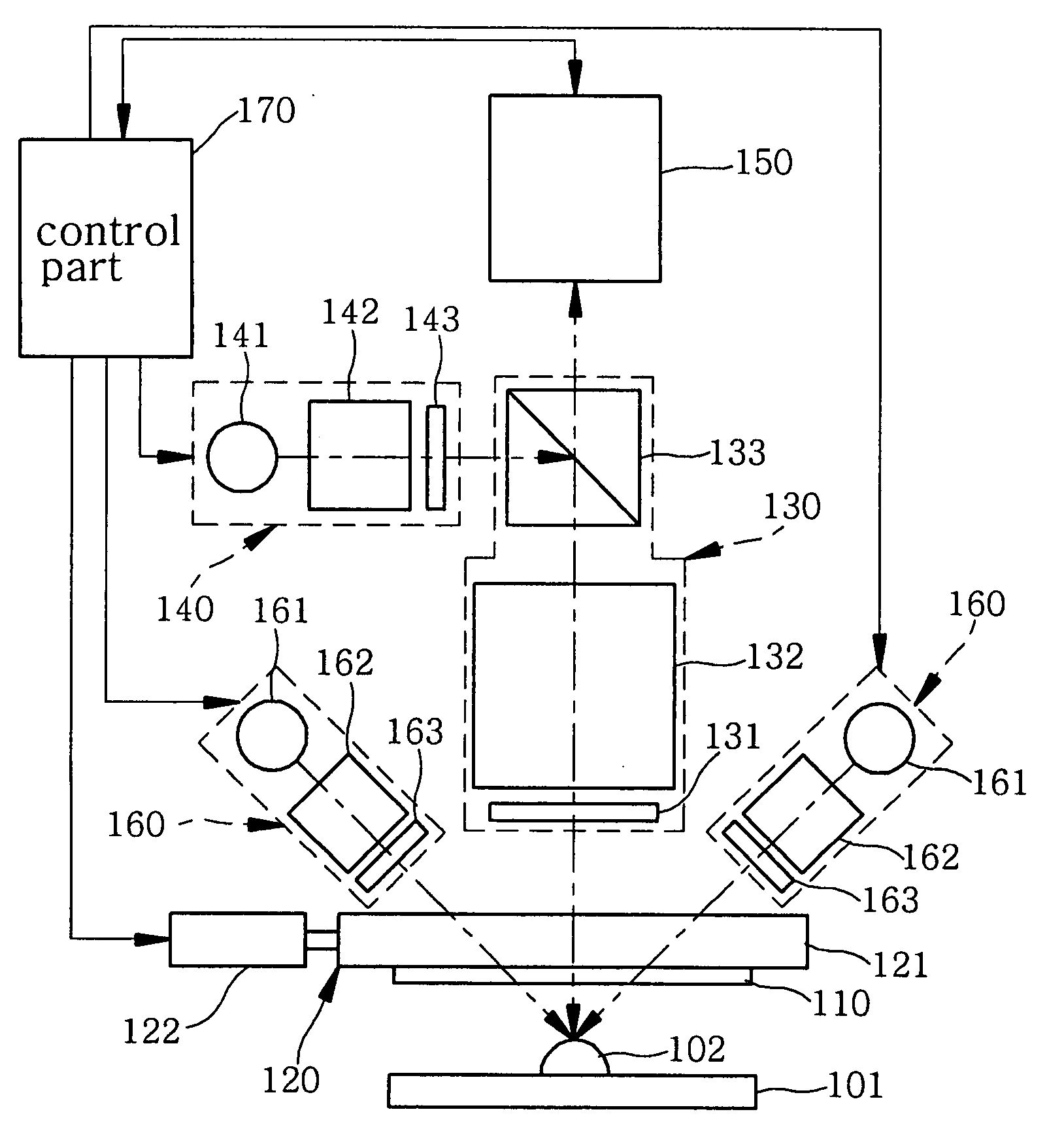
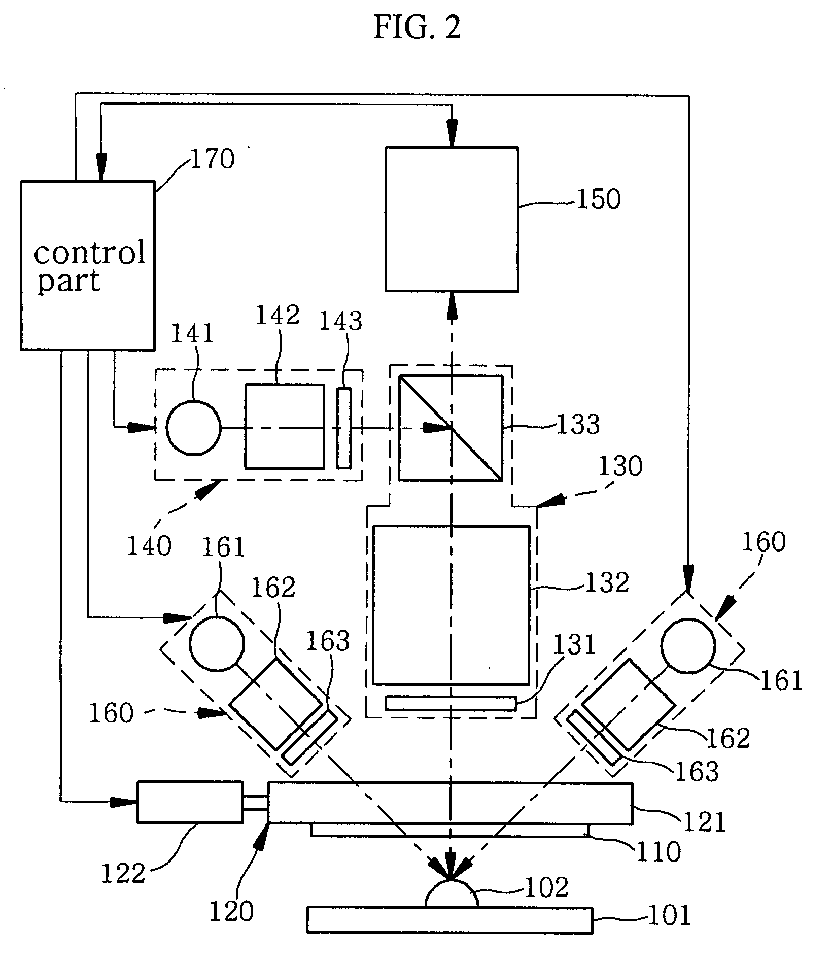
[0021]As shown in FIGS. 2 and 3, a 3D shape measuring apparatus using a shadow moire according to the present invention includes a grating 110 being placed above a work stage 101 to move a test object 102 to a measuring location, a grating moving part 120 including the grating 110 and moving the grating 110, a beam splitter part 130 being provided above the grating 110 to emit a first light towards the grating 110 or pass a reflected image of the test object 102, which is reflected via the grating 110, a subsidiary illuminating part 140 being provided on one side surface of the beam splitter part 130 to emit the first light towards the beam splitter part 130, an image sensor 150 being provided above the beam splitter part 130 to take the reflected image passed through the beam splitter part 140, a plurality of illuminating parts being provided to be inclined a...


PUM


Abstract

A 3D shape measuring apparatus using a shadow moire, which can measure a 3D shape of a test object by selectively switching on/off a plurality of illuminating parts irrespective of a form of the test object is provided. The 3D shape measuring apparatus using the shadow moire includes a grating 110, a grating moving part 120, a beam splitter part 130 being provided above the grating 110 to direct a first light source towards the grating 110 or pass a reflected image of a test object 102 reflected via the grating 110, a subsidiary illuminating part 140 being provided on one surface of the beam splitter part 130 to emit the first light towards the beam splitter part 130, an image sensor 150 being provided above the beam splitter part 130 to take the reflected image having passed through the beam splitter part 130, a plurality of illuminating parts 160 being inclined a predetermined angle of the viewing axis of the image sensor 140 to be positioned above the grating 110 and to be spaced apart from each other with an equivalent angle and emit a second light towards the grating 110, and a control part 170 controlling the grating moving part 120, the subsidiary illuminating part 140, the image sensor 150, and the plurality of illuminating parts 160, and thereby, transferring the image which is captured by the image sensor 150, in order to calculate a 3D shape of the test object 102, and controlling the plurality of illuminating parts 160 to be selectively switched on/off according to a shape of the test object 102.

Description

BACKGROUND OF THE INVENTION[0001]1. Field of the Invention[0002]The present invention relates to a 3-dimensional (3D) shape measuring apparatus using a shadow moire, and more particularly, to a 3D shape measuring apparatus using a shadow moire, which can measure a 3D shape of a test object by selectively switching on / off a plurality of illuminating parts irrespective of a shape of the test object.[0003]2. Description of the Related Art[0004]A 3D shape measuring apparatus using a conventional moire will be described with reference to FIG. 1.[0005]As shown in FIG. 1, the 3D shape measuring apparatus using the conventional moire includes a control part 10, a work stage 20, a projection part 30, a rotation part 40, and an image sensor 50. The control part 10 controls the 3D shape measuring apparatus, and thereby measures a 3D shape of a test object 21 by using a reflected image which is captured by the image sensor 50. In this instance, the test object 21 is moved to a measuring locatio...

Claims


Application Information

Patent Timeline
IPC IPC(8): G01B11/24
CPCG01B11/25G01B11/2433G01N21/45G02B27/60G01N2021/456
Inventor JEON, MOON YOUNGYUN, SANG KYU
Owner KOHYOUNG TECH
Why Eureka
Try Eureka