Aircraft Having A Ring-Shaped Wing Structure

a wing structure and ring-shaped technology, applied in the field of aircraft, can solve the problems of unmanned helicopters risking secondary disasters, difficult to approach afflicted areas, large blades of aircraft falling off, etc., and achieve the effect of flying and maneuvering safely

Inactive Publication Date: 2007-09-20
RIEKEN WILLIAM D +2
View PDF13 Cites 63 Cited by
  • Summary
  • Abstract
  • Description
  • Claims
  • Application Information

AI Technical Summary

Benefits of technology

[0008] It is, therefore, an objective of the present invention to provide an aircraft which is able to fly and maneuver safely in places like inhabitable areas that are dangerous for helicopters to fly and maneuver in.

Problems solved by technology

There are some cases in which it is difficult to approach afflicted areas of large-scale disasters such as huge earthquakes because of severed transit systems.
However, an unmanned helicopter risks setting off a secondary disaster.
For example, when it tries to approach afflicted areas more closely by descending for a more detailed investigation, taking advantage of its mobility, there is a risk that its large blades will collide with the wall of a building.
However, the GEOBAT, which has an all-circular wing structure, has the disadvantage that it has a considerably smaller opening in the center relative to the aircraft size, therefore it provides not much space for components to be mounted there.

Method used


Image

  • Aircraft Having A Ring-Shaped Wing Structure
  • Aircraft Having A Ring-Shaped Wing Structure
  • Aircraft Having A Ring-Shaped Wing Structure

Examples


Embodiment Construction

[0035] Referring to the figures, the following description will discuss embodiments of the present invention. In the following description, only unmanned aircraft are described as the embodiments of the present invention; however, the present invention can be also applied to manned aircraft.

[0036] In addition, the aircraft of the present invention can be used in various kinds of fields other than being used for gathering information at a time of disaster. For example, they can be used for the purposes of security or monitoring from the sky, for scientific and atmosphering sensing, as a sensor platform, or for recreation or transportation.

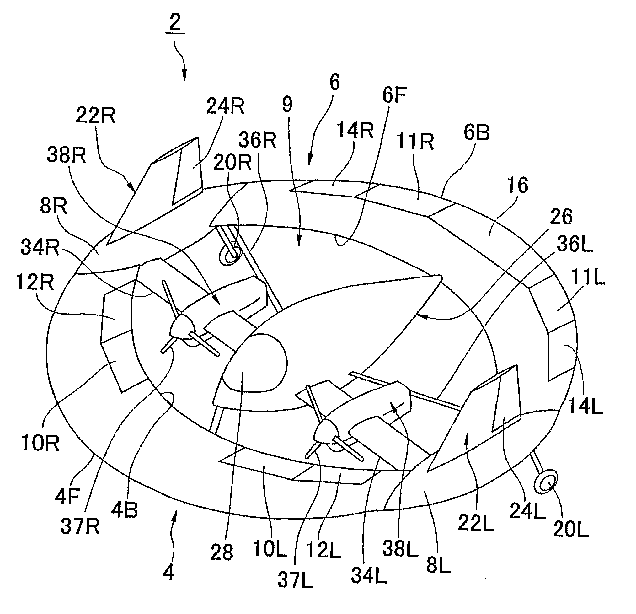
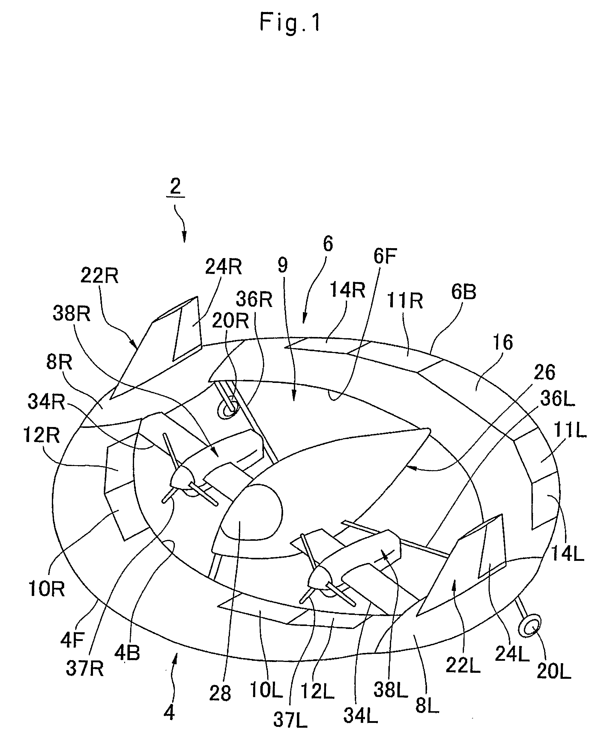
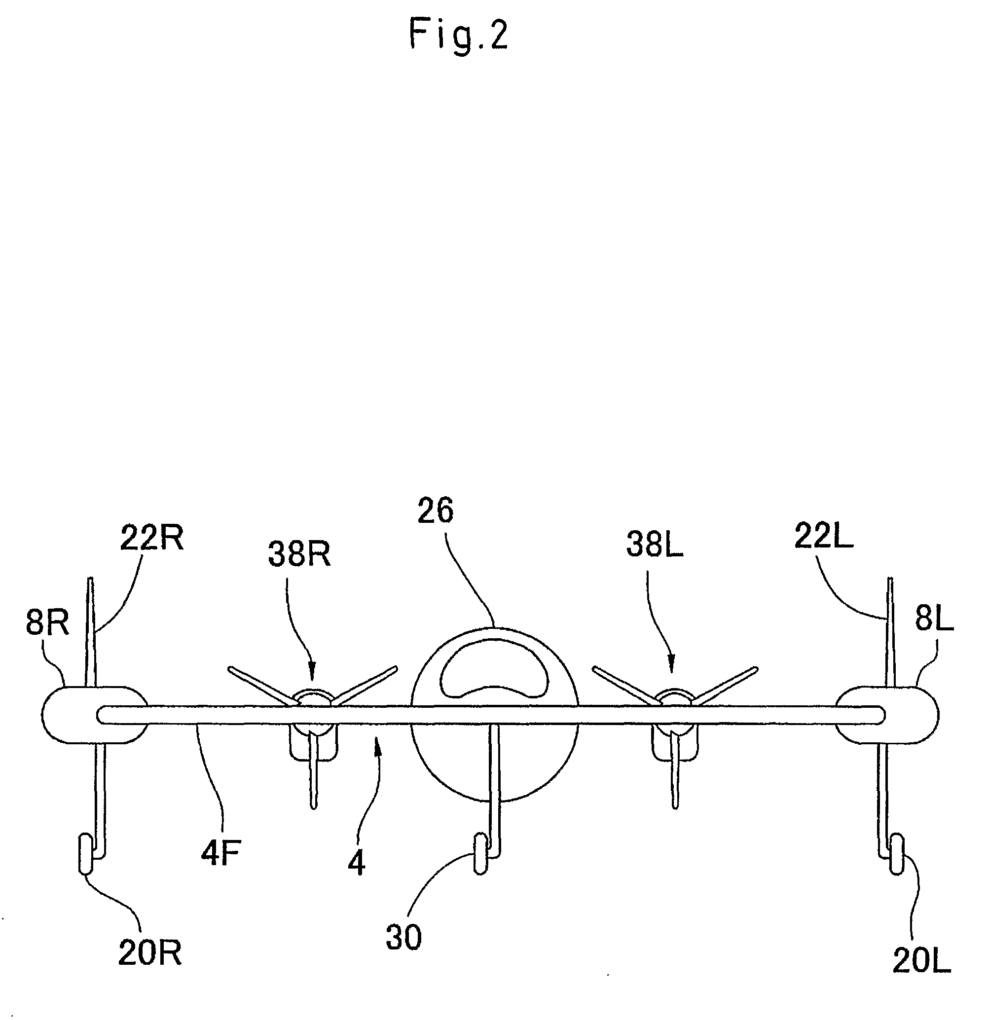
[0037] FIGS. 1 to 6 show an aircraft according to one embodiment of the present invention. The aircraft 2 includes a front wing 4, a rear wing 6, both having an almost identical boomerang shape as the main wings, and a pair of wing boxes 8L and 8R, having an aerodynamic shape, which connect the front wing 4 and the rear wing 6 at airfoil tips. The...


PUM


Abstract

The aircraft includes a boomerang-shaped front wing (4), curving gibbously to the front, having a leading edge (4F), a trailing edge (4B) and the first and second airfoil tips (4E1, 4E2), a boomerang-shaped rear wing (6), curving gibbously to the back, having a leading edge (6F), a trailing edge (6B) and the third and forth airfoil tips 86E1, 6E2), the first wing box (8L) connecting the first airfoil tip of the front wing and the third airfoil tip of the rear wing, the second wing box (8R) connecting the second airfoil tip of the front wing and the fourth airfoil tip of the rear wing. The trailing edge of the front wing, the leading edge of the rear wing, and the internal surfaces of the wing boxes form a center opening (9) having, at least in part, elliptical shape.

Description

BACKGROUND OF THE INVENTION [0001] 1. Field of the Invention [0002] This present invention generally relates to aircraft, especially to aircraft having a boomerang shape wing structure (hereinafter, in this specification, the word “boomerang shape” includes both round type of boomerang and straight-line type of boomerang). [0003] 2. Description of the Related Art [0004] There are some cases in which it is difficult to approach afflicted areas of large-scale disasters such as huge earthquakes because of severed transit systems. Consequently, unmanned aircraft with surveillance cameras collecting information from the sky, to survey for victims and afflicted areas, are currently being researched. [0005] However, an unmanned helicopter risks setting off a secondary disaster. For example, when it tries to approach afflicted areas more closely by descending for a more detailed investigation, taking advantage of its mobility, there is a risk that its large blades will collide with the wall...

Claims


Application Information

Patent Timeline
Patent Type & Authority Applications(United States)
IPC IPC(8): B64C39/06B64C39/08
CPCB64C39/06
Inventor RIEKEN, WILLIAM D.BENSCHEIDT, JOERG
Owner RIEKEN WILLIAM D
Why Eureka
Try Eureka