Multi-stance aerial device control and display

a multi-stance, aerial device technology, applied in the direction of instruments, vehicle maintenance, liquid/fluent solid measurement, etc., can solve the problems of inability to fully deploy the stabilizer, fire departments have no way to plan ahead, and stop any further deployment of the aerial device, etc., to achieve the effect of increasing the tip load, reducing reliability, and increasing the tip load

Active Publication Date: 2021-04-13
SPARTAN FIRE LLC
View PDF16 Cites 1 Cited by
  • Summary
  • Abstract
  • Description
  • Claims
  • Application Information

AI Technical Summary

Benefits of technology

[0027]The system's graphics will change as the device is repositioned, so that the operator sees only that information needed for that configuration, which allows the user to safely maneuver the aerial device.
[0030]As will be understood, embodiments of the present invention allow the operator to use the aerial device to the greatest extent possible without the reduced reliability that comes with a device that attempts to measure dynamic load.
[0031]Further, embodiments of the present invention can be utilized with fire departments that are capable of fully deploying the stabilizers, such as suburban fire departments, and can benefit from the higher tip loads that go with the wider deployment of the stabilizers. Embodiments can also be used with fire departments that are willing to deal with a smaller tip load in order to allow for a more narrow deployment of the stabilizers, such as urban fire departments that will often times have to deal with obstructions, such as cars or narrow streets, that prevent the full deployment of the stabilizers during use of the aerial device.

Problems solved by technology

However, this can be problematic, as in practice full deployment of the stabilizers is not always possible, especially in urban areas where parked cars and other obstacles often times will obstruct the full deployment of the stabilizers.
Further, due to the uncertainty of where the next fire will start or where the next call will take them, the fire departments have no way to plan ahead or, often times, even the time to fully assess their location to make a determination of where to optimally place the firetruck to allow for the full deployment of the stabilizers before using the aerial device.
Next, the traditional aerial devices and platforms used outside of the United States, such as in Europe, will typically use a more complex system to measure the active load on the aerial ladder that takes into consideration the deployment position of the stabilizers.
Typically, the systems outside of the United States will utilize a computer control system coupled to load sensors that will detect when the device is reaching its maximum load depending on position of the stabilizers and will stop any further deployment of the aerial device before the aerial device exceeds its maximum load and becomes unstable.
However, the problem with the systems typically used outside the United States is that system relies on using sensitive load sensors that inevitably are damaged due to the generally rough nature of fighting fires.
As will be understood, when the load sensors in the system is damaged it becomes extremely problematic as most fire departments only have a limited number of firetrucks and often times even fewer firetrucks that are fitted with an aerial device.
Therefore, any downtime caused by the damaged load sensor can put the lives of the firefighters and the people they are trying to help in danger by not providing the firefighters with a firetruck or additional firetrucks with an aerial device, which may be needed to safely put out a fire or to safely rescue a person trapped in a building that is on fire.
Further, due to the load sensors being easily damaged current fire departments employing systems using load sensors are required to conduct high levels of maintenance and service on the sensors even when they are not currently damaged to avoid the situation where they need to deploy the aerial device while at a call and then find out that they cannot deploy the aerial device due to a load sensor that has been damaged since the last time the aerial device was deployed.

Method used


Image

  • Multi-stance aerial device control and display
  • Multi-stance aerial device control and display
  • Multi-stance aerial device control and display

Examples


Embodiment Construction

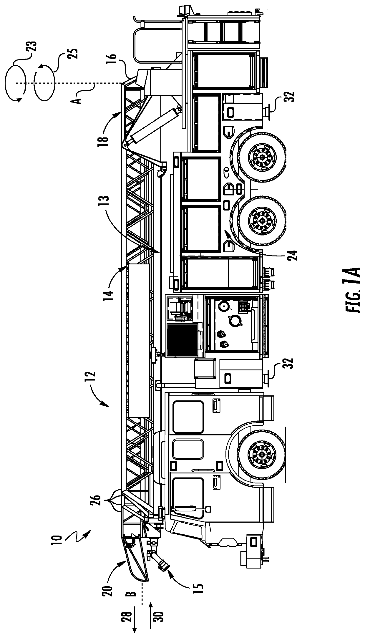
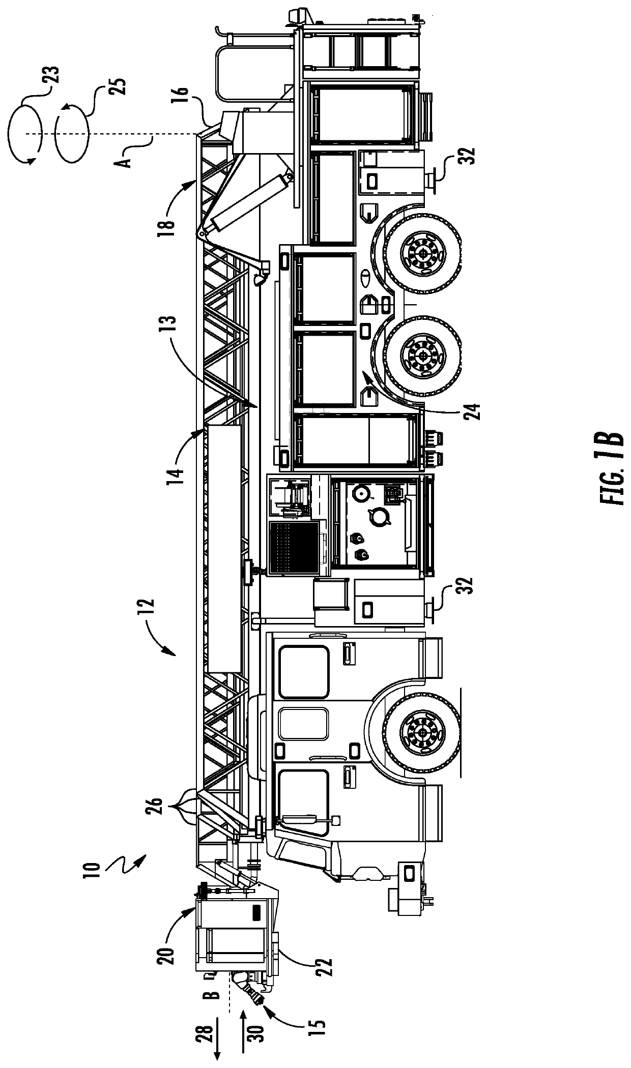
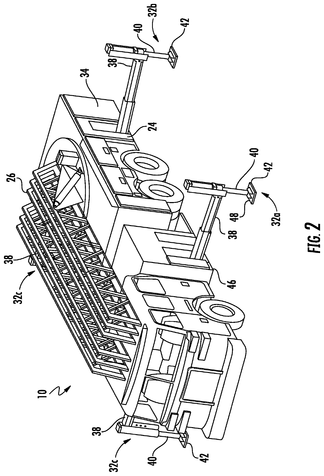
[0080]FIGS. 1-6 illustrate a vehicle 10 with an aerial and platform device 12. The aerial device 12 includes a ladder 14 and a control means 16. In FIG. 1A the ladder 14 of the aerial device 12 has a first end 18 that is coupled to the control means 16 and a second end 20 that is free. In FIG. 1B the ladder of an the aerial device 12 has a first end 18 that is coupled to the control means 16 and a second end 20 that is coupled to a platform 22.

[0081]Extending along the ladder 14 of the aerial device 12 may be piping 13 designed to allow fluid, such as water, to flow from the piping 13 when the fluid is sufficiently pressurized. At the end of the piping 13 can be a fluid monitor nozzle 15 that can meter the flow of the pressurized fluid being expelled from the piping 13.

[0082]The control means 16 of the vehicle 10 can rotate the ladder 14 and / or ladder 14 and platform 22 about vertical axis A in a first direction 23 and a second direction 25 that is opposite the first direction 23 wh...


PUM


Abstract

An electronic display for an aerial device is provided. The electronic display replaces a traditional load chart including the operational parameters of the aerial device being used. The electronic display electrically connected with a computer control system connected to a sensor for collecting at least one piece of data relating to the operational parameters of the aerial device. The computer control system calculating the current operational parameter of the aerial device based on the at least one piece of data collected by the sensor and updating the operational parameters of the aerial device and displaying a graphical representation of the updated operational parameters on the electronic display.

Description

FIELD OF THE INVENTION[0001]This invention generally relates to vehicle mounted firefighting aerial devices consisting of ladders or booms, with or without platforms, and more particularly to an aerial device control and display system for use therewith.BACKGROUND OF THE INVENTION[0002]Traditional firefighting aerial devices used by fire departments in the United States leave control of the aerial device in the hands of the operator who is responsible for referencing a physical load chart that describes the operational parameters of the device in text and graphics.[0003]Factors that affect the operational parameters of the aerial device include the number of people on the ladder and / or in the platform, the placement of the people on the ladder and / or in the platform, the extension of the aerial device, the elevation of the aerial device, the rotation of the aerial device, and whether the aerial device is charged with or flowing water.[0004]In addition, typically fire trucks that dep...

Claims


Application Information

Patent Timeline
Patent Type & Authority Patents(United States)
IPC IPC(8): B60S9/04G01F1/00G01C5/00G01V11/00A62C31/28E06C5/42A62C27/00A62C31/00
CPCB60S9/04G01C5/00G01F1/00G01V11/002A62C27/00A62C31/005A62C31/28E06C5/42E06C5/18E06C5/14E06C5/36E06C7/16
Inventor LACKORE, JR., JAMES ROGER
Owner SPARTAN FIRE LLC
Why Eureka
Try Eureka