Determining visibility distances based on a dynamic field of view of a vehicle

a dynamic field of view and vehicle technology, applied in distance measurement, process and machine control, instruments, etc., can solve the problems of insufficient scenario understanding and decision, insufficient idea to increase the performance of sensors to achieve safe maneuvering decisions,

Active Publication Date: 2022-03-29
CONTINENTAL AUTOMOTIVE GMBH
View PDF7 Cites 0 Cited by
  • Summary
  • Abstract
  • Description
  • Claims
  • Application Information

AI Technical Summary

Benefits of technology

[0030]Based on the visibility distance a decision making process e.g. for determining if a certain maneuver can safely be performed can be provided with additional data in order to improve the basis for the decision. This increases safety of the decision making process and reduces the probability of bad decisions and therefore also the probability of accidents. In particular the safety of overtaking maneuvers of autonomous vehicles can be increased based on the visibility distance.
[0067]Based on the visibility distance(s) including information about the area of the road or lanes where the at least one sensor can observe or “see” a reliable and informed decision whether to change the driving lane can be made. Thus, a reliable way to autonomously change a driving lane is provided.

Problems solved by technology

Especially overtaking maneuvers are a big challenge in autonomous driving.
One problem is that the idea to increase performance of sensors to achieve safe decision making for maneuvers like the overtaking maneuver may not be sufficient, because sensors mounted on vehicles will never be able to detect blind spots (“behind a corner”), e.g. the area behind an object such as a vehicle on an adjacent lane.
This means that in a complex traffic scenario there will always be areas that will be tagged as unknown not only because the sensors are limited in distance of detection, but because of occlusions (or: obstruction) due to objects in the surroundings of the vehicle.
Hence, including more and more high technology devices in the object detection system of vehicles may be beneficial for the precision of the acquired data, but may in some cases not be sufficient for scenario understanding and decision making regarding complex maneuvers like the overtaking maneuver.

Method used


Image

  • Determining visibility distances based on a dynamic field of view of a vehicle
  • Determining visibility distances based on a dynamic field of view of a vehicle
  • Determining visibility distances based on a dynamic field of view of a vehicle

Examples


Embodiment Construction

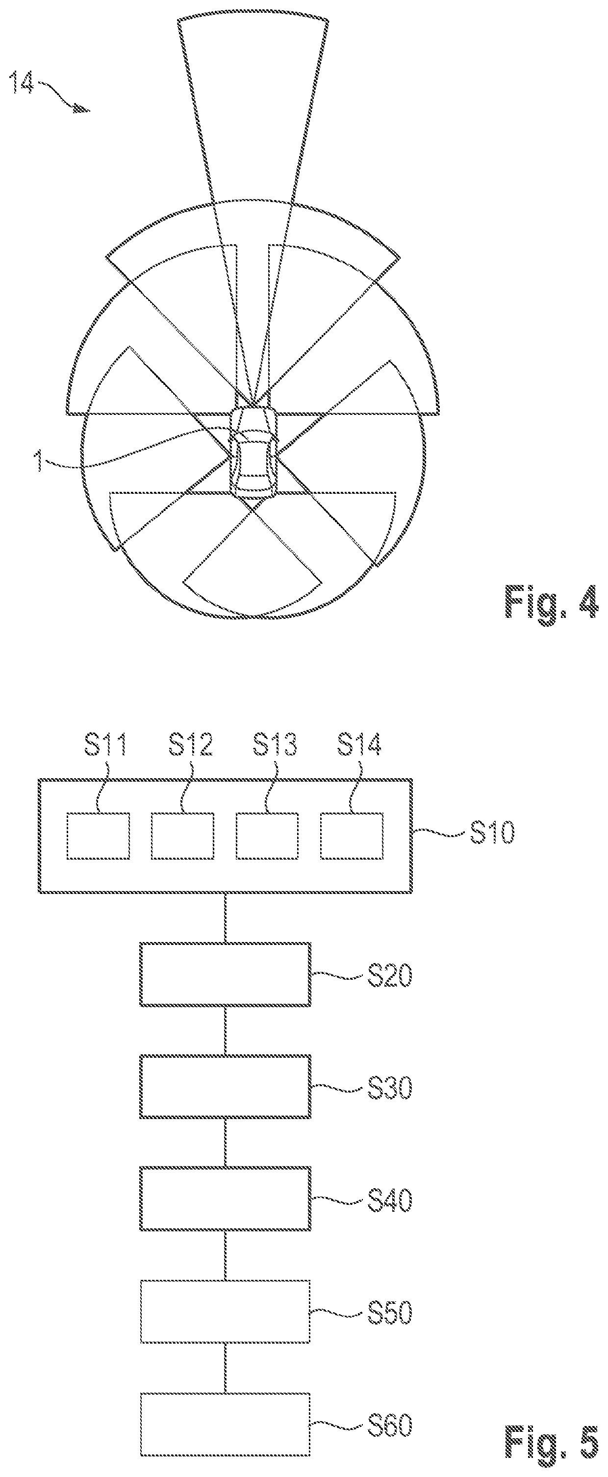
[0076]A system for determining visibility distances based on a dynamic Field of View, FoV, of an ego vehicle according to an embodiment of the second aspect of the present invention will be described with respect to FIG. 1A to FIG. 4 in the following.

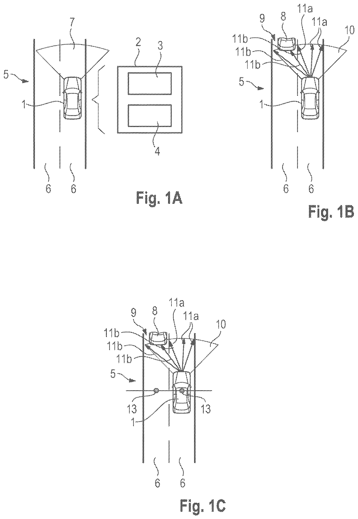
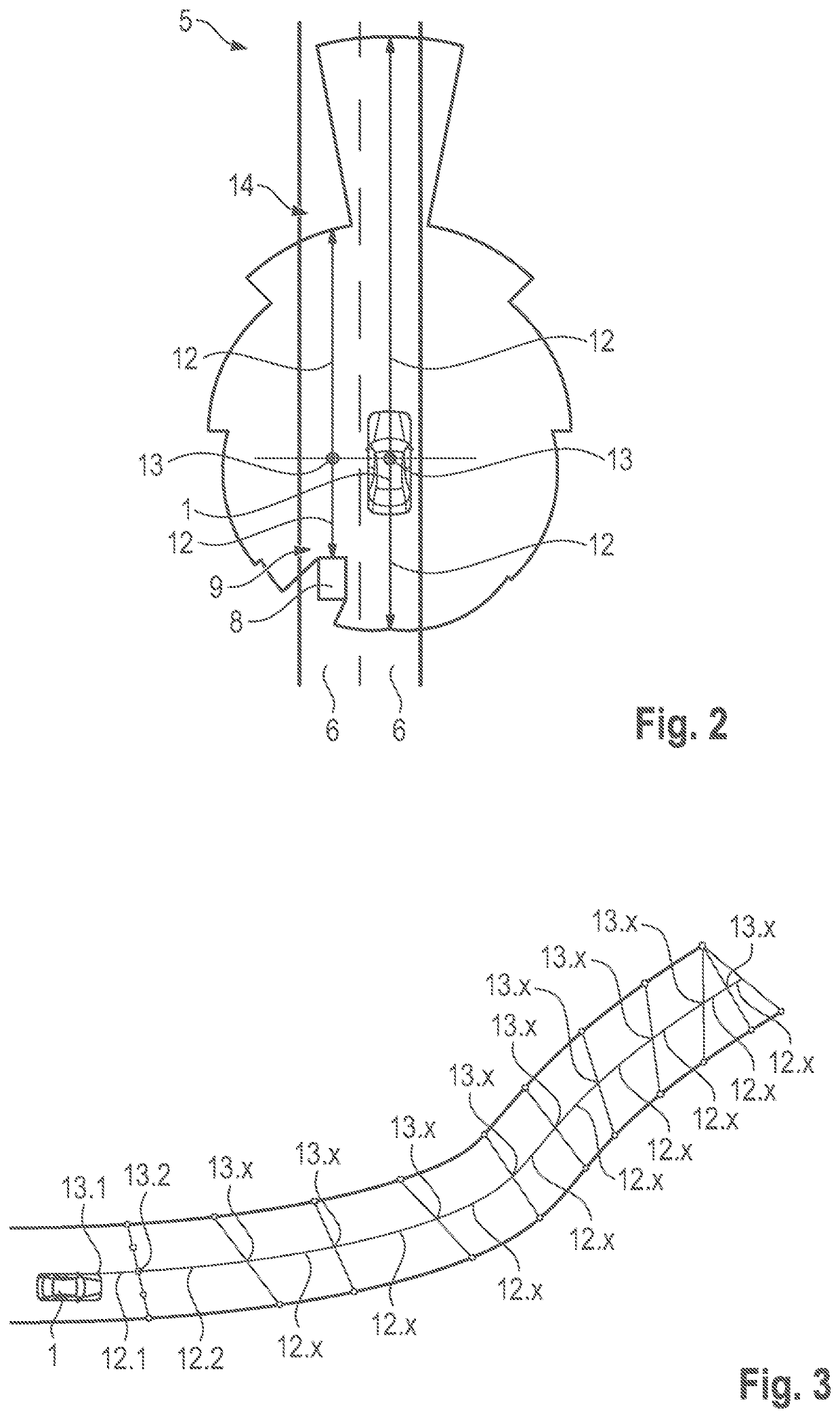
[0077]In FIG. 1A an ego vehicle 1, specifically an autonomous car 1 is schematically depicted. The autonomous car 1 comprises a system 2 configured for determining visibility distances based on a dynamic field of view, FoV, of the autonomous car 1.

[0078]The system 2 comprises at least one sensor 3 that can be a LiDAR sensor, a radar sensor, an ultra-sonic sensor and / or the like. The system 2 further comprises a controller 4. The controller can be a separate unit with a processor, memory and interface or be part of an autonomous driving controller of the autonomous car 1. The autonomous car 1 is moving on a road 5 with two lanes 6. The road 5 and / or lanes 6 are delimited by map polygons in a map of the surroundings of the autonomous car ...


PUM


Abstract

A method and a system determine visibility distances based on a dynamic Field of View (FoV) of a subject vehicle. A vehicle incorporates the system. Map polygons are created, each of which determines edges of a road in a map of the surroundings of the subject vehicle. Further, visible areas are determined in the map by intersecting the map polygons with the dynamic FoV. Based on the visible areas, a visibility distance for the road is determined.

Description

FIELD OF THE INVENTION[0001]The present invention relates to a method for determining visibility distances based on a dynamic Field of View (FoV) of a subject vehicle, also called an ego vehicle, and to a system configured to determine visibility distances based on a dynamic Field of View (FoV) of an ego vehicle as well as to a vehicle comprising the system.BACKGROUND INFORMATION[0002]Vehicles, particularly autonomous vehicles like autonomous cars and unmanned ground vehicles capable of sensing their environment and navigating without human input, are equipped with sensors that can detect objects in the surroundings of the vehicle. Such vehicles combine a variety of techniques to perceive their surroundings, including radar, laser light, GPS, odometry and computer vision. Advanced control systems of autonomous vehicles interpret sensory information to identify appropriate navigation paths, as well as obstacles and relevant signage. The autonomous vehicles must have control systems t...

Claims


Application Information

Patent Timeline
Patent Type & Authority Patents(United States)
IPC IPC(8): G01C22/00G05D1/00B60W30/18
CPCB60W30/18163G05D1/0088B60W2400/00B60W2554/00G05D2201/0213G01C21/28G08G1/166B60W2420/52B60W2420/54B60W2552/53G06V20/56B60W2520/14B60W2420/403B60W2554/802B60W2552/15B60W2552/30B60W2554/4041B60W2554/20B60W2554/4029B60W2554/804
Inventor BURCA, CRISTIAN
Owner CONTINENTAL AUTOMOTIVE GMBH
Why Eureka
Try Eureka