Ejection restoration apparatus for liquid ejection head and image forming apparatus comprising ejection restoration apparatus

a liquid ejection head and restoration apparatus technology, applied in the direction of printing, other printing apparatus, etc., can solve the problems of ink dries, increase in viscosity of ink, and print defects, so as to reduce the time required for maintenance and consumption of ink

Inactive Publication Date: 2007-09-27
FUJIFILM CORP
View PDF2 Cites 22 Cited by
  • Summary
  • Abstract
  • Description
  • Claims
  • Application Information

AI Technical Summary

Benefits of technology

[0022]As described above, according to the present invention, a mechanism which restores liquid ejection at nozzles by means of suctioning is combined with a mechanism which wipes the nozzle surface, and the ink consumption and time required for maintenance can be reduced by suctioning (only) a nozzle which is suffering an abnormality. Moreover, it is possible to carry out maintenance by suctioning and wiping the nozzles of the liquid ejection head, without causing adverse effects on other nozzles which are not suctioned.

Problems solved by technology

An inkjet printer of this kind records information by ejecting ink directly from very fine nozzles, and there is a possibility of printing defects caused by ejection defects or ejection failures due to abnormality of the state of the nozzles.
In particular, in an on-demand type of inkjet printer which ejects ink only when an image signal is input, there may be nozzles which do not perform ink ejection over a long period of time.
In this case, the ink solvent evaporates from the nozzles, the viscosity of the ink increases or the ink dries, and ejection defects may occur.
Phenomena of this kind may also occur if a recording operation is not carried out for a long period of time.
However, in the related art, during the maintenance of the inkjet head, it is necessary to carry out a wiping operation and a suctioning operation by capping, successively, and there is a possibility that the composition becomes complex.
Moreover, since a large amount of maintenance time is required in order to carry out these operations, then throughput may decline.
Furthermore, if ink is suctioned from the whole of the inkjet head, then there is a large amount of wasted ink.
Moreover, in the invention described in Japanese Patent Application Publication No. 6-328729, suctioning by capping is not sufficient.
Since no consideration at all is given to this point in Japanese Patent Application Publication No. 6-328729, then air leakage occurs during the suctioning by means of the cap and it is difficult to carry out sufficient suctioning.
Moreover, since no consideration is given to carrying out wiping by a blade moving over the nozzle surface, then the rigidity of the elastic body may be too high and satisfactory wiping may not be achieved by means of the blade, and ink may therefore be left on the nozzle surface.

Method used


Image

  • Ejection restoration apparatus for liquid ejection head and image forming apparatus comprising ejection restoration apparatus
  • Ejection restoration apparatus for liquid ejection head and image forming apparatus comprising ejection restoration apparatus
  • Ejection restoration apparatus for liquid ejection head and image forming apparatus comprising ejection restoration apparatus

Examples


second embodiment

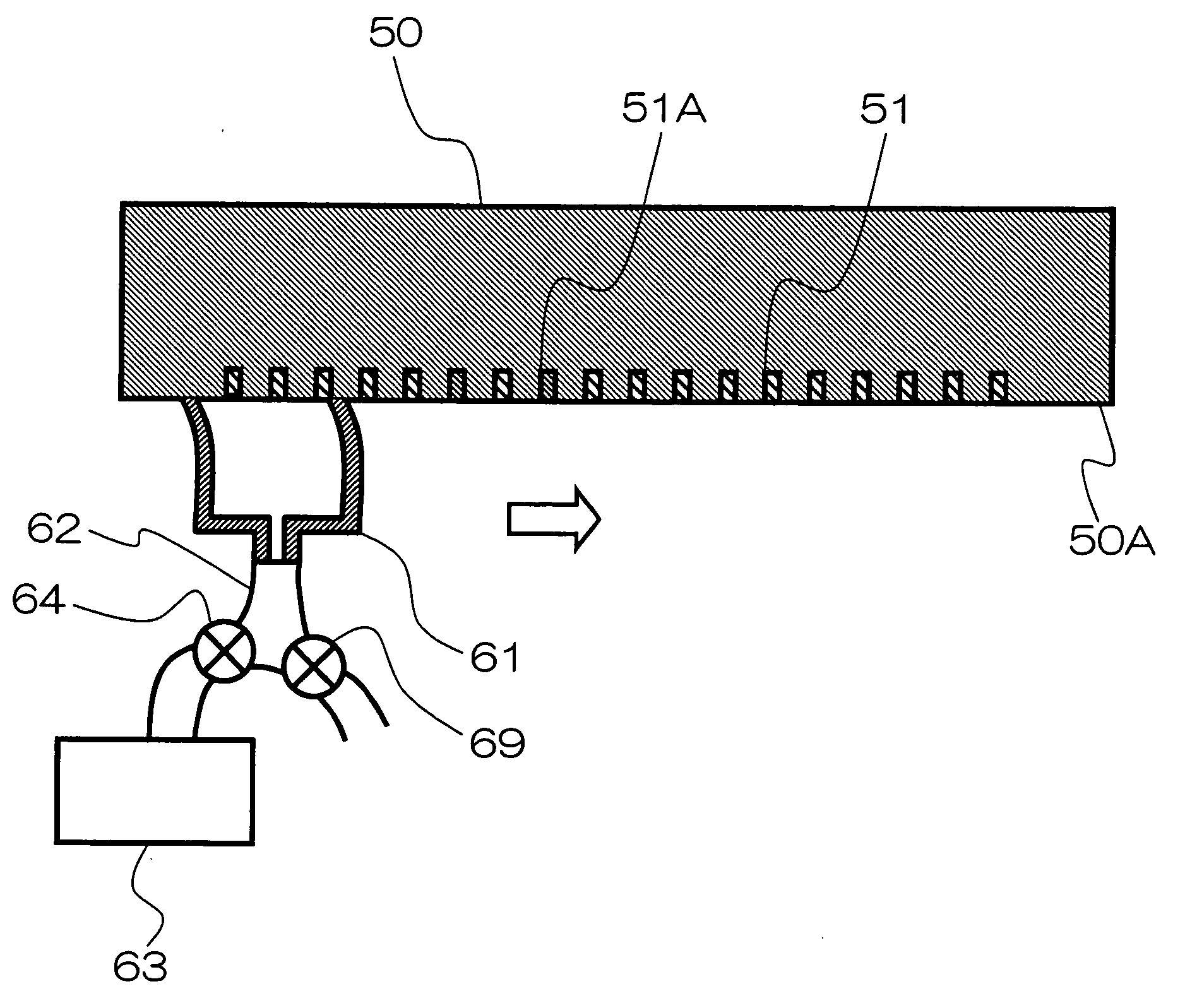
[0094]Next, the ejection restoration apparatus for a liquid ejection head according to a second embodiment of the present invention is described below with reference to FIG. 7. The second embodiment relates to members 61A and 61B of the capping member 61 which are each made of an elastic material, and the members 61A and 61B make contact with the nozzle surface 50A. In the second embodiment, a composition is adopted in which the member 61B on the rear side in terms of the direction of movement of the capping member 61 with respect to the nozzles 51, has a rigidity lower than the rigidity of the member 61A on the front side.

[0095]More specifically, when maintenance of the nozzle surface 50A of the liquid ejection head is performed, the capping member 61 is moved along the nozzle surface 50A in the direction of the arrow in FIG. 7. The elastic body forming the front side member 61A, which is situated on a front side in terms of the direction of movement of the capping member 61, is fo...

third embodiment

[0097]Next, the ejection restoration apparatus for a liquid ejection head according to a third embodiment of the present invention is described below with reference to FIG. 8. In the third embodiment, a second capping member 165 which covers the first capping member 161 is provided.

[0098]More specifically, in addition to the first capping member 161 which is capable of performing movement for suctioning and wiping the nozzles 51 of the nozzle surface 50A, a second capping member 165 is further provided so as to cover the first capping member 161 and the whole of the nozzle surface 50A of the liquid ejection head 50. The second capping member 165 is connected to a suction pump 167 via an ink flow channel 166, and the pressure (P2) in the space defined by the second capping member 165 and the nozzle surface 50A of the liquid ejection head 50 is set to a negative pressure compared to the atmospheric pressure (P0). The first capping member 161 is connected to the suction pump 163 via th...

fourth embodiment

[0102]Next, an ejection restoration apparatus for a liquid ejection head according to a fourth embodiment of the present invention is described below with reference to FIG. 9. In the fourth embodiment, a second capping member 165 is provided on the front side of a first capping member 161 in terms of the direction of movement of the first capping member 161.

[0103]More specifically, the second capping member 165 which covers a portion of the nozzle surface 50A of the liquid ejection head 50 is provided on the front side, in terms of the movement direction of the first capping member 161 which is capable of performing a movement for suctioning and wiping of the nozzles 51 of the nozzle surface 50A. The first capping member 161 and the second capping member 165 make contact with each other at a boundary between these capping members 161 and 165, and are united. The second capping member 165 is connected to a suction pump 167 via an ink flow channel 166, and the pressure (P2) in the spa...


PUM


Abstract

The ejection restoration apparatus for a liquid ejection head having a plurality of nozzles which are disposed in a planer nozzle surface and from which liquid is ejected, includes: a first suction cap which covers a partial region of the planer nozzle surface and which has a contact portion being constituted by an elastic body and making contact with the planer nozzle surface, the partial region being smaller than area of the planer nozzle surface in which the nozzles are disposed and being larger than cross-sectional area of one of the nozzles; a suction cap movement device which moves the first suction cap in parallel with the planer nozzle surface while causing the contact portion of the first suction cap to make contact with the planer nozzle surface; a nozzle abnormality detection device which detects an abnormal nozzle suffering an abnormality, in the nozzles; and a suction control device which causes the first suction cap to suction the liquid in the abnormal nozzle detected by the nozzle abnormality detection device, wherein the first suction cap is moved on the planer nozzle surface in a state where a space defined by the first suction cap and the planer nozzle surface is set to a pressure lower than an atmospheric pressure, so that the first suction cap fulfills both a wiping function and a suctioning function.

Description

BACKGROUND OF THE INVENTION[0001]1. Field of the Invention[0002]The present invention relates to a restoration apparatus for a liquid ejection head and an image forming apparatus comprising a restoration apparatus for a liquid ejection head, and more particularly, to an ejection restoration apparatus for nozzles which can be used when a nozzle blockage or the like has occurred in an apparatus which forms an image by ejecting ink onto a recording medium, or the like, and to an image forming apparatus comprising such an ejection restoration apparatus.[0003]2. Description of the Related Art[0004]As an image forming apparatus in the related art, an inkjet printer (inkjet recording apparatus) is known, which comprises an inkjet head (liquid ejection head) having an arrangement of a plurality of liquid ejection nozzles and which records an image on a recording medium by ejecting ink (liquid) from the nozzles toward the recording medium while causing a relative movement between the inkjet ...

Claims


Application Information

Patent Timeline
Patent Type & Authority Applications(United States)
IPC IPC(8): B41J2/165
CPCB41J2/165
Inventor KUSAKARI, TSUTOMU
Owner FUJIFILM CORP
Why Eureka
Try Eureka