Micro ballpoint pen and printing apparatus

a technology of ballpoint pen and printing apparatus, which is applied in the direction of typewriters, nibs, coatings, etc., can solve the problems of inability to print dashed lines, ink consumption and printing resolution limitation, and inability to control exactly the falling position of ink droplets, so as to reduce ink consumption and printing apparatus

Inactive Publication Date: 2013-04-04
ELECTRONICS & TELECOMM RES INST
View PDF4 Cites 2 Cited by
  • Summary
  • Abstract
  • Description
  • Claims
  • Application Information

AI Technical Summary

Benefits of technology

[0011]Even other example embodiments of the inventive concept provide a micro ballpoint pen capable of reducing ink consumption and a printing apparatus including the same.

Problems solved by technology

However, there are technical difficulties in controlling exactly a falling position of the ink droplet, changing a printing thickness range, preventing ink from being blurred, and printing a continuous line.
By contrast, all of screen printing, offset printing, flexography, and gravure may need an engraving resulting in an increase in ink consumption and a limitation in printing resolution.
However, for the near-field electro-spinning method, a line is printed using a high electric field, it is hard to print a dashed line, a bulge may occur at an end of line, and there is a limitation in using various kinds of inks.
In addition, since the method is sensitive to a distortion of electric field, it is hard to prevent an interference issue, especially in the case of using a multi-nozzle.
Furthermore, there is a dip-pen or nano fountain-pen method, which is developed from an atomic force microscope (AFM) measuring a fine structure in an atomic level, but this method suffers from a very expensive apparatus cost and a small printing area.
So far, there has been a technical difficulty in applying a ballpoint pen for a high resolution printing apparatus.
This is because it is hard to control exactly a ball gap, which is formed between a ball and a pen tip, and through which ink is outflowed by a rolling ball.
In other words, it is hard to control an ejecting amount of ink exactly.

Method used


Image

  • Micro ballpoint pen and printing apparatus
  • Micro ballpoint pen and printing apparatus
  • Micro ballpoint pen and printing apparatus

Examples


Embodiment Construction

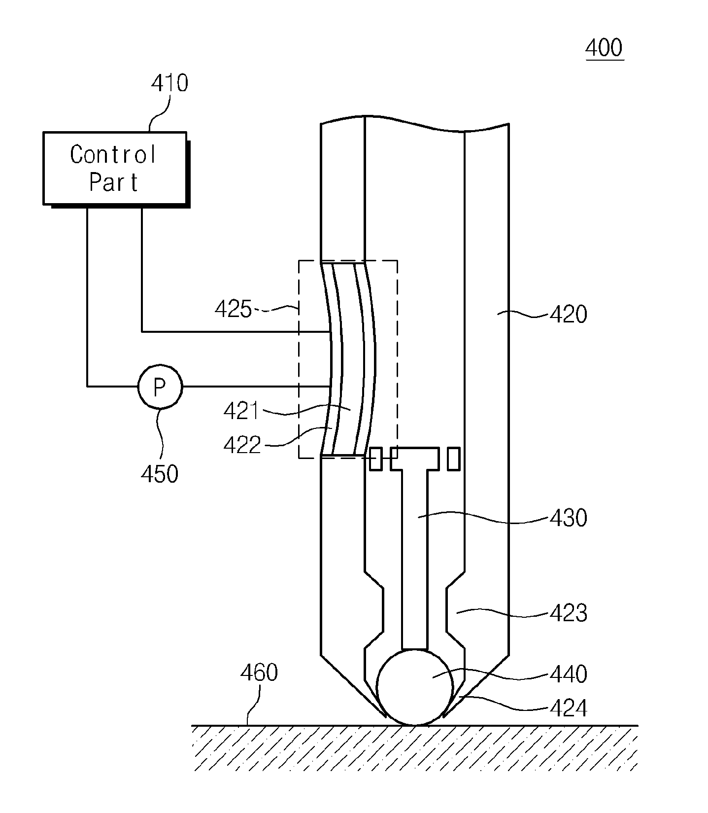
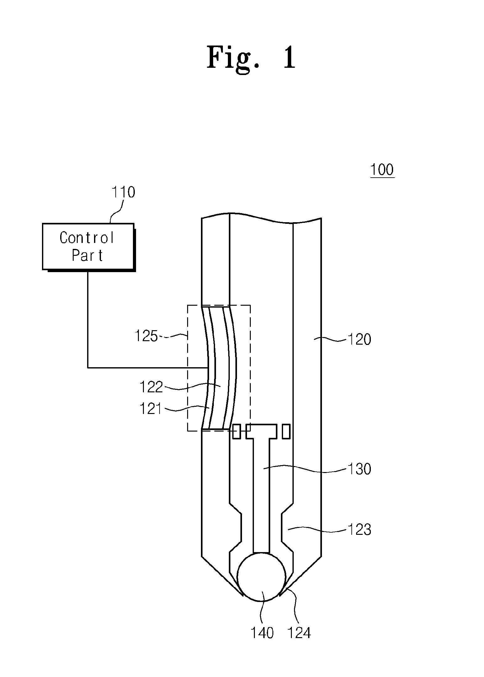
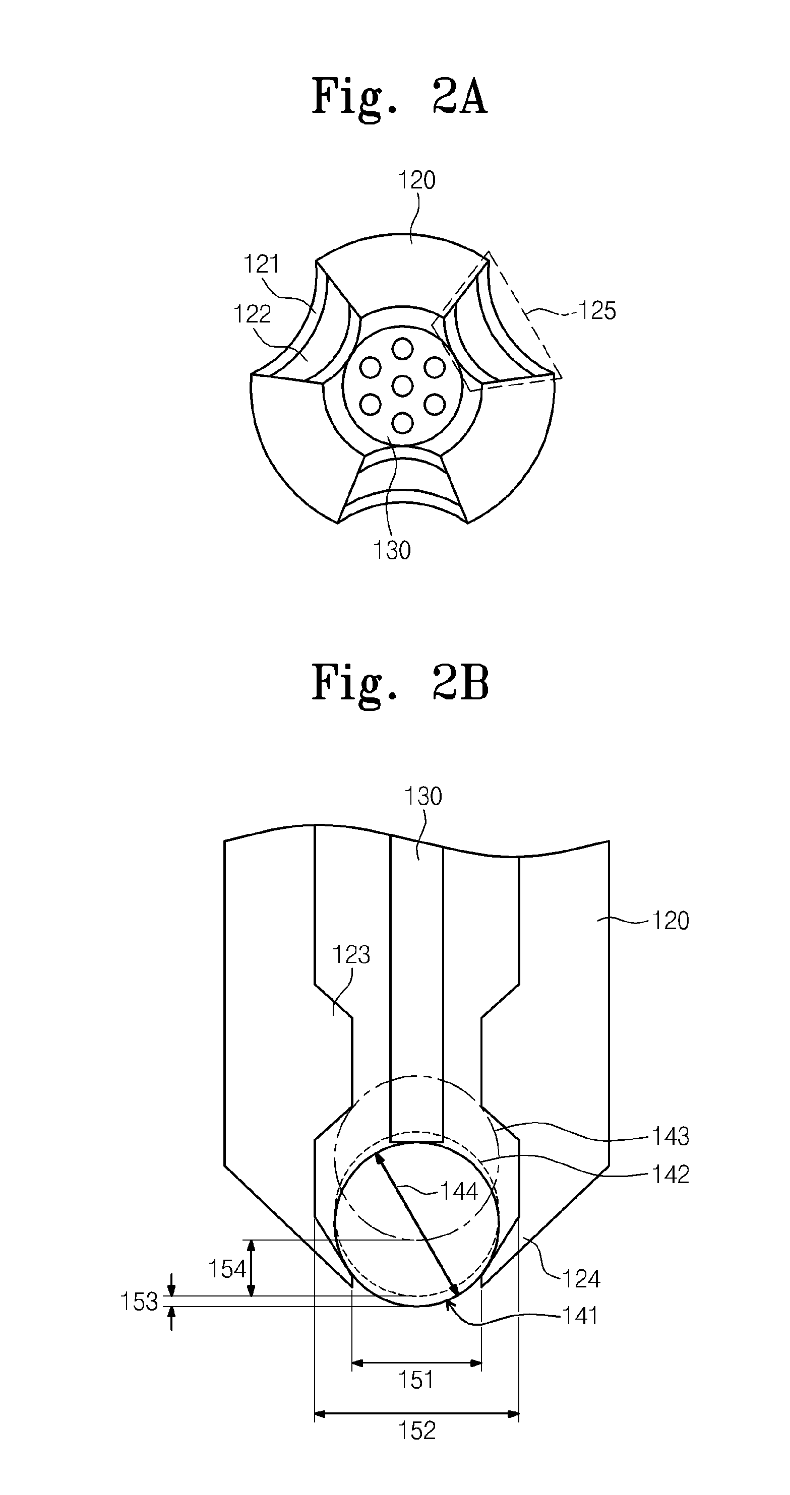
[0044]Example embodiments of the inventive concepts will now be described more fully with reference to the accompanying drawings, in which example embodiments are shown. Example embodiments of the inventive concepts may, however, be embodied in many different forms and should not be construed as being limited to the embodiments set forth herein; rather, these embodiments are provided so that this disclosure will be thorough and complete, and will fully convey the concept of example embodiments to those of ordinary skill in the art. In the drawings, the thicknesses of layers and regions are exaggerated for clarity. Like reference numerals in the drawings denote like elements, and thus their description will be omitted.

[0045]It will be understood that when an element is referred to as being “connected” or “coupled” to another element, it can be directly connected or coupled to the other element or intervening elements may be present. In contrast, when an element is referred to as bein...


PUM


Abstract

Provided are a micro ballpoint pen enabling to print directly straight, oblique, curved, dashed, broken and wavy lines and a printing apparatus including the same. The micro ballpoint pen may include a tip body including a caulking portion, at least one inner protrusion, and at least one expansible or shrinkable elastic portion, a ball provided between the caulking portion and the inner protrusion, the ball contacting and rolling on a target printing object to eject ink onto the target printing object, a supporting bar pressing the ball toward the caulking portion to form an ink outflowing channel between the caulking portion and the ball, and a control part expanding or shrinking the elastic portion to control the ink outflowing channel.

Description

CROSS-REFERENCE TO RELATED APPLICATIONS[0001]This U.S. non-provisional patent application claims priority under 35 U.S.C. §119 to Korean Patent Application No. 10-2011-0099871, filed on Sep. 30, 2011, in the Korean Intellectual Property Office, the entire contents of which are hereby incorporated by reference.BACKGROUND OF THE INVENTION[0002]Embodiments of the inventive concepts relate to a micro ballpoint pen and a printing apparatus, and in particular, a micro ballpoint pen configured to perform a printing operation in a direct contact manner, and a printing apparatus including the same.[0003]Electronic devices may be fabricated using fine and elaborated printing methods, e.g., inkjet printing, screen printing, offset printing, flexography, and gravure. For example, these printing methods may be applied to various technical fields, such as a flat-panel display device (e.g., a liquid crystal display (LCD), an organic light emitting device (OLED), an organic thin film transistor (OT...

Claims


Application Information

Patent Timeline
Patent Type & Authority Applications(United States)
IPC IPC(8): B05C1/08
CPCB43K1/086B41J3/36B41F31/08B41F33/00
Inventor LIM, SANGCHULYANG, YONG SUKAHN, SEONGDEOKCHO, KYOUNG IK
Owner ELECTRONICS & TELECOMM RES INST
Why Eureka
Try Eureka