Inkjet printing apparatus and a purging method therefor

a technology of purging method and printing apparatus, which is applied in the field of printing apparatus, can solve the problems of difficult to remove the bubbles that have entered the feed path, the nozzles are clogged, and the possibility of clogging, so as to achieve the effect of reducing ink consumption and facilitating suction

Active Publication Date: 2013-03-28
RICOH KK
View PDF3 Cites 15 Cited by
  • Summary
  • Abstract
  • Description
  • Claims
  • Application Information

AI Technical Summary

Benefits of technology

[0021]According to this invention, the decompression device is operated in a state of the cap placed in contact with the inkjet head, and both of the ink feed control valve and decompression control valve closed. This places the ink in a state of choke suction in which negative pressure forces the ink toward the cap. When the ink feed control valve is opened to decompress the inside of the cap, the ink will be discharged at a burst into the cap along with bubbles. After the predetermined time, the ink feed control valve is closed, the decompression device is stopped, and the cap is moved away from the inkjet head. This series of operations is constituted mainly of operation timing of the ink feed control valve, decompression control valve, and decompression device, thereby realizing the choke suction with ease. Since the ink feed control valve is closed upon lapse of the predetermined time after ink discharge, a wasteful discharge of the ink can be inhibited and ink consumption can be reduced.

Problems solved by technology

This has resulted in an increased possibility of the nozzles getting clogged (non-discharge of ink droplets).
Clogging of the nozzles is caused by the ink droplets plugging up the nozzles, or bubbles entering feed paths of the ink droplets.
With such purging, while the ink droplets plugging up the nozzles can be removed, it is difficult to remove the bubbles having entered the feed paths.
This poses problems of complicating control and consuming the ink excessively.
The second conventional apparatus requires the diaphragm pumps mounted on the feed pipes, which leads to a complicated construction and a cost increase.
It is also necessary to control the diaphragm pumps, resulting in complicated control.
Besides, there is again a problem of consuming the ink excessively.

Method used


Image

  • Inkjet printing apparatus and a purging method therefor
  • Inkjet printing apparatus and a purging method therefor
  • Inkjet printing apparatus and a purging method therefor

Examples


Embodiment Construction

[0027]One embodiment of this invention will be described hereinafter with reference to the drawings.

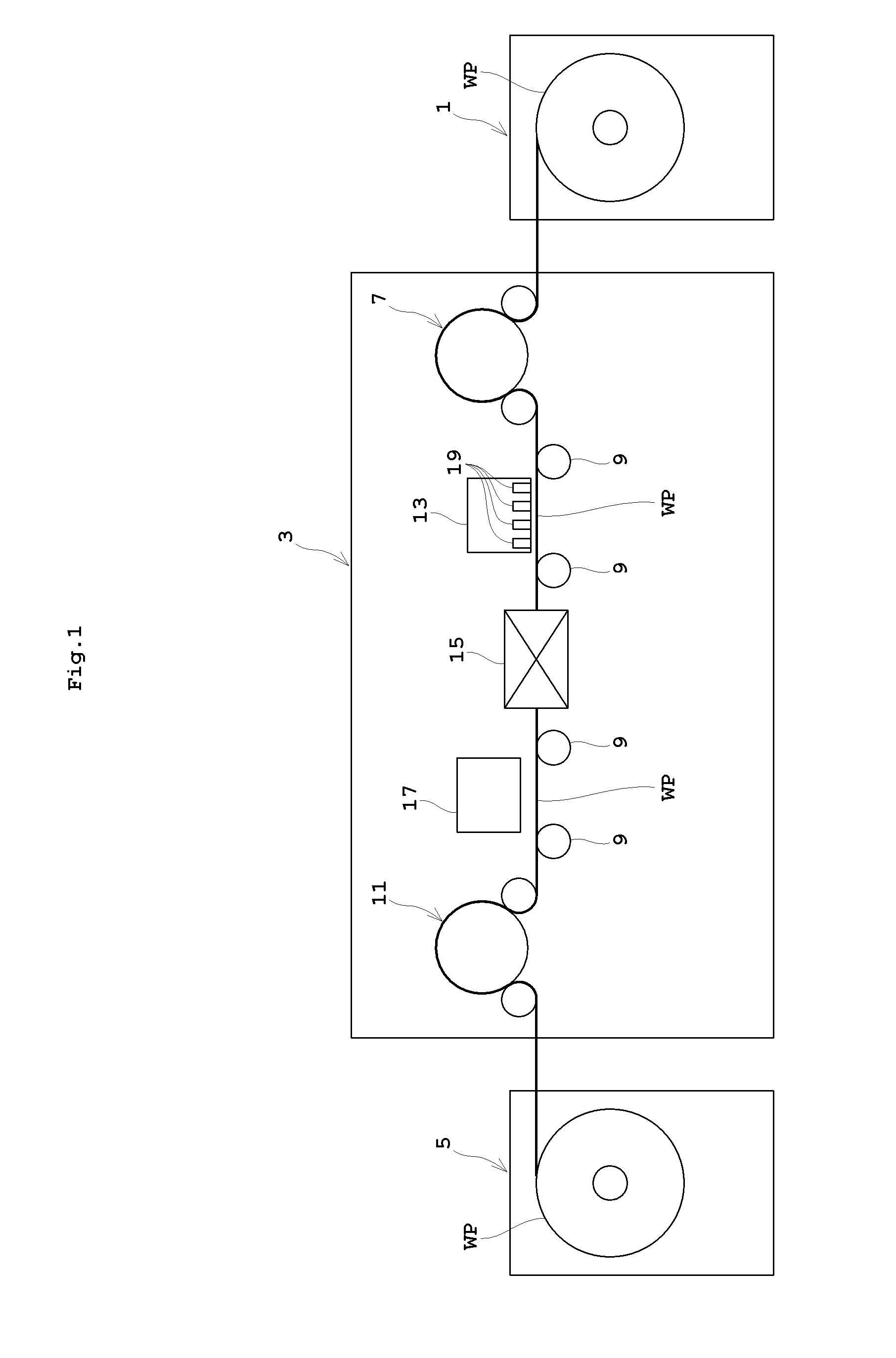
[0028]FIG. 1 is a schematic view showing an entire inkjet printing system according to this invention. The inkjet printing system according to this invention includes a paper feeder 1, an inkjet printing apparatus 3, and a paper discharger 5. The paper feeder 1 feeds web paper WP stored in a roll form as a printing medium, for example. The inkjet printing apparatus 3 performs printing on the web paper WP fed thereto. The paper discharger 5 winds up printed web paper WP in a roll form.

[0029]The paper feeder 1 holds the web paper WP in the roll form to be rotatable about a horizontal axis, and unwinds the web paper WP to feed it to the inkjet printing apparatus 3. The paper discharger 5 winds up the web paper WP printed by the inkjet printing apparatus 3 about a horizontal axis. Regarding the side from which the web paper WP is fed as upstream and the side to which the web paper WP is d...


PUM


Abstract

An inkjet printing apparatus carries out printing by moving an inkjet head and printing paper relative to each other. The inkjet head has a plurality of nozzles for discharging ink droplets. The apparatus includes a feed pipe connected to each nozzle of the inkjet head for feeding ink thereto, an ink feed control valve mounted on the feed pipe for controlling circulation of the ink, a cap for blocking the plurality of nozzles of the inkjet head, a decompression device for decompressing an inside of the cap, decompression piping for connecting the cap and the decompression device, a decompression control valve mounted on the decompression piping for controlling communication between the cap and the decompression device, and a controller.

Description

BACKGROUND OF THE INVENTION[0001](1) Field of the Invention[0002]This invention relates to an inkjet printing apparatus for printing on printing paper by discharging ink droplets from an inkjet head while moving the inkjet head and the printing paper relative to each other, and to a purging method therefor.[0003](2) Description of the Related Art[0004]An inkjet printing apparatus performs printing by applying ink to printing paper from an inkjet head spaced from the printing paper. With printing resolution becoming higher, a plurality of nozzles of the inkjet head have an increasingly refined structure. This has resulted in an increased possibility of the nozzles getting clogged (non-discharge of ink droplets). Clogging of the nozzles is caused by the ink droplets plugging up the nozzles, or bubbles entering feed paths of the ink droplets. One method of eliminating the clogging consists in what is called purging, which is carried out by attaching a cap to the nozzles of the inkjet h...

Claims


Application Information

Patent Timeline
Patent Type & Authority Applications(United States)
IPC IPC(8): B41J2/165
CPCB41J2/16585B41J2/16532B41J2/19B41J2/17596B41J2/16523
Inventor YAMAMOTO, TAKAHARU
Owner RICOH KK
Why Eureka
Try Eureka