Droplet discharging apparatus, method of controlling droplet discharging apparatus and image forming apparatus including droplet discharging apparatus

a technology droplet discharging apparatus, which is applied in the field of droplet discharging apparatus, a method of controlling an image forming apparatus including a droplet discharging apparatus, can solve the problems of colorant sedimentation, failure, and lowering image quality, and achieve the effect of reducing electrical energy consumption and ink consumption

Active Publication Date: 2016-09-22
RICOH KK
View PDF6 Cites 10 Cited by
  • Summary
  • Abstract
  • Description
  • Claims
  • Application Information

AI Technical Summary

Benefits of technology

[0013]The present invention is made in light of the above problems, and provides a droplet discharging apparatus capable of detecting a sedimentation status of ink pigment in various sedimentary inks, and reducing electrical energy consumption and ink consumption.

Problems solved by technology

However, there is a problem that the colorant sediments if the pigment ink is left for a long time.
If the sedimentary ink is left, physical property values (viscosity or the like) of the ink change because the ink cannot retain a normal condition in which the pigment is uniquely mixed.
As a result, a printing failure occurs due to lowering of discharging characteristics, or lowering of image quality such as the concentration is not uniform occurs.
However, according to the technique of Patent Document 1, as will be explained later, there is a problem that slight change of the viscosity of the ink cannot be detected because variation of ON resistor / ON time of a switching unit directly influences on the above described period Ts and the peak value Em of the first half-wave varies largely.
Thus, there is a problem that the pump is always periodically driven and power consumption is increased.

Method used


Image

  • Droplet discharging apparatus, method of controlling droplet discharging apparatus and image forming apparatus including droplet discharging apparatus
  • Droplet discharging apparatus, method of controlling droplet discharging apparatus and image forming apparatus including droplet discharging apparatus
  • Droplet discharging apparatus, method of controlling droplet discharging apparatus and image forming apparatus including droplet discharging apparatus

Examples


Embodiment Construction

[0038]The invention will be described herein with reference to illustrative embodiments. Those skilled in the art will recognize that many alternative embodiments can be accomplished using the teachings of the present invention and that the invention is not limited to the embodiments illustrated for explanatory purposes.

[0039]It is to be noted that, in the explanation of the drawings, the same components are given the same reference numerals, and explanations are not repeated.

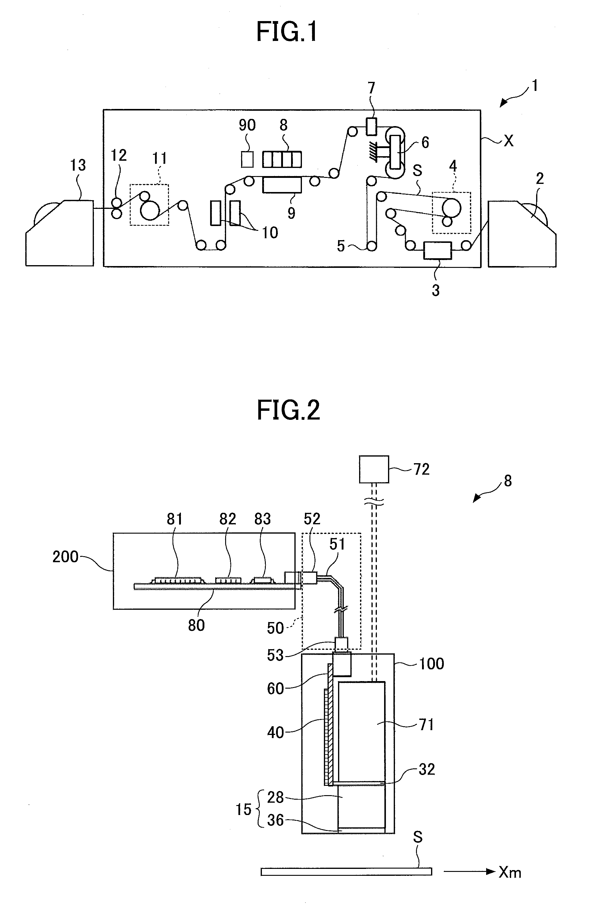
[0040]FIG. 1 is a view schematically illustrating a structure of an on-demand line scanning inkjet recording apparatus (image forming apparatus). The inkjet recording apparatus 1 includes an inkjet recording apparatus body X, a recording medium supplying unit 2 and a recording medium collecting unit 13.

[0041]The inkjet recording apparatus body X includes a regulation guide 3, an inner feed unit 4, a dancer roller 5, an Edge Position Controller (EPC) 6, a meandering amount detector 7, an inkjet recording module ...


PUM


Abstract

A droplet discharging apparatus includes a recording head that includes pressure chambers, piezoelectric elements, and an in-head reservoir, provided near the pressure chambers; a liquid circulation unit that includes a liquid reservoir and circulates liquid between the in-head reservoir and the liquid reservoir; a drive waveform generation unit that generates a drive waveform that drives each of the piezoelectric elements; a remaining oscillation detection unit that detects remaining oscillation generated in at least one of the pressure chambers after driving the respective piezoelectric element; a status determining unit that determines a sedimentation status of a component in liquid in the in-head reservoir based on the detected remaining oscillation; and a control unit that controls a liquid circulation operation of the liquid circulation unit in order to dissolve the sedimentation status of the component in the liquid in the in-head reservoir based on the determined sedimentation status.

Description

BACKGROUND OF THE INVENTION[0001]1. Field of the Invention[0002]The present invention relates to a droplet discharging apparatus, a method of controlling a droplet discharging apparatus and an image forming apparatus including a droplet discharging apparatus.[0003]2. Description of the Related Art[0004]An inkjet printer is widely known as an image forming apparatus in which ink is injected on a recording medium. Such an inkjet printer includes a recording head, and prints on a recording medium by discharging ink droplets from nozzles formed at the recording head toward the recording medium. Further, an inkjet printer is known that includes a unit capable of discharging a special color ink (white, for example) or a magnetic material ink in addition to general YMCK inks.[0005]For ink used for such an inkjet printer (printer apparatus), a dye ink and a pigment ink are used. The pigment ink has a feature that it is brightly colored as the pigment ink uses pigment as colorant and the pig...

Claims


Application Information

Patent Timeline
Patent Type & Authority Applications(United States)
IPC IPC(8): B41J2/045
CPCB41J2/04581B41J2/04588B41J2/16508B41J2/1652B41J2/16523B41J2/16585
Inventor TOBITA, KATSUHIRO
Owner RICOH KK
Why Eureka
Try Eureka