
Systems and methods for posterior dynamic stabilization of the spine

a dynamic stabilization and posterior technology, applied in the field of spinal disorders and pain, can solve the problems of affecting the ability of spinal motion segments to properly function, eventual deterioration or disorder, and debilitating pain, and achieves low cost, minimal invasiveness, and convenient installation.

Inactive Publication Date: 2007-09-27
EXACTECH INC
View PDF58 Cites 84 Cited by
  • Summary
  • Abstract
  • Description
  • Claims
  • Application Information

AI Technical Summary

Benefits of technology

The system enables effective stabilization and motion mimicry of healthier vertebral segments, facilitating the treatment of various spinal disorders and pain conditions, including degenerative disc disease and failed fusions, with improved ease of installation and adaptability.

Problems solved by technology

Traumatic, inflammatory, metabolic, synovial, neoplastic and degenerative disorders of the spine can produce debilitating pain that can affect a spinal motion segment's ability to properly function.
Often, a disorder in one location or spinal component can lead to eventual deterioration or disorder, and ultimately, pain in another.
However, fusion is only as good as the ability to restore disc height to relieve the pain by taking pressure off the nerves, nerve roots, and / or articulating surfaces—i.e., facet joints and end plates of the vertebral bodies.
In many current systems, however, attachment and deployment of such a cross-connector is difficult.

Method used


Image

  • Systems and methods for posterior dynamic stabilization of the spine
  • Systems and methods for posterior dynamic stabilization of the spine
  • Systems and methods for posterior dynamic stabilization of the spine

Examples


second embodiment

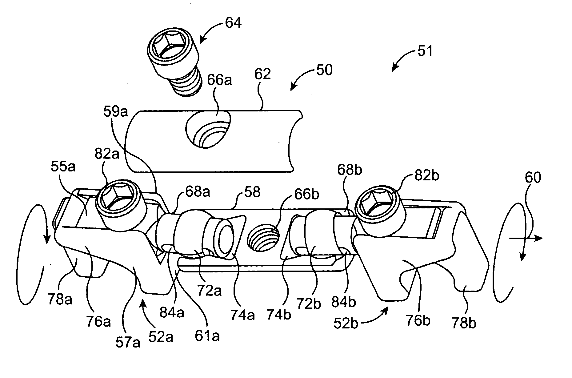
[0090]FIG. 4 shows the invention, with some elements in common with the embodiment of FIGS. 2-3. A cross-connector system 90 is shown with two-part rod attachment elements 92a and 92b, and a cross connector 91. In this embodiment, the cross connector 91 includes a dynamic element 114. The dynamic element 114 may include any type of element that can provide a degree of motion to the cross connector 91, including the types of dynamic elements disclosed in U.S. patent Ser. No. 11 / 427,738. For example, the dynamic element may provide a resilient bias, such as with a flexible portion or a spring. One or more characteristics of dynamic element 91 may be adjustable (adjustment means not shown but may be, e.g., a rotatable set screw), such as an adjustment to the range of motion and / or a force applied to resist motion.

[0091] The cross connector 91 further includes depending cylindrical projections 112a and 112b, these depending from opposite sides of the dynamic element 114. Into each cylin...

third embodiment

[0097]FIG. 5(A)-(D) illustrates a cross-connector system 120 according to the invention, this embodiment incorporating certain features of the aforedescribed embodiments.

[0098] In FIG. 5(A), two stabilizing rods 110a and 110b are engaged by two corresponding two-part rod attachment elements 118a and 118b. The rod attachment elements 118a and 118b each have a biasing section or hook section 126a and 126b, respectively, which operate in conjunction with sliding clamps 128a and 128b to grasp rods 110a and 110b.

[0099] In more detail, sliding clamps 128a and 128b each have corresponding hook-engaging elements 132a and 132b (see FIG. 5(D)) which are slidingly received by corresponding holes defined in the hook sections 126a and 126b. At the opposite end of each of sliding clamps 128a and 128b is a section defining an upwardly-facing recess 134a and 134b. Two rod-locking screws 138a and 138b are provided to tighten the sliding clamps 128a and128b to the hook sections 126a and 126b, and th...


PUM


Abstract

A spinal cross-connector for connecting two stabilization rods installed in a patient's spine is provided. The cross-connector includes novel rod attachment elements dynamically connected together by connector elements. The cross-connector provides multi-dimensional adjustability for easy and accurate installation with full lock-down.

Description

CROSS-REFERENCE TO RELATED APPLICATIONS [0001] This application is a continuation-in-part of U.S. patent application Ser. No. 11 / 427,738, filed on Jun. 29, 2006, entitled “Systems and methods for posterior dynamic stabilization of the spine”, which is a continuation-in-part of U.S. patent application Ser. No. 11 / 436,407, filed on May 17, 2006, entitled “Systems and methods for posterior dynamic stabilization of the spine”, which is a continuation-in-part of U.S. patent application Ser. No. 11 / 033,452, filed on Jan. 10, 2005, entitled “Systems and methods for posterior dynamic stabilization of the spine”, which is a continuation-in-part of U.S. patent application Ser. No. 11 / 006,495, filed on Dec. 6, 2004, entitled “Systems and methods for posterior dynamic stabilization of the spine”, which is a continuation-in-part of U.S. patent application Ser. No. 10 / 970,366, filed on Oct. 20, 2004, entitled “Systems and methods for posterior dynamic stabilization of the spine”. U.S. patent appl...

Claims


Application Information

Patent Timeline
Patent Type & Authority Applications(United States)
IPC IPC(8): A61B17/58
CPCA61B17/7004A61B17/7005A61B17/7052A61B17/7032A61B17/7037A61B17/7019A61B17/58
Inventor ALTARAC, MOTIHAYES, STANLEYREGLOS, JOEYGUTIERREZ, ROBERTFLAHERTY, J.
Owner EXACTECH INC
Learn More