

System and methods for posterior dynamic stabilization of the spine
- Summary
- Abstract
- Description
- Claims
- Application Information
AI Technical Summary
Benefits of technology
Problems solved by technology
Method used
Image

Examples
second embodiment
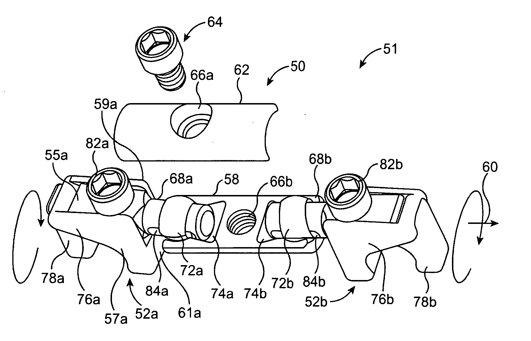
[0090]FIG. 4 shows the invention, with some elements in common with the embodiment of FIGS. 2-3. A cross-connector system 90 is shown with two-part rod attachment elements 92a and 92b, and a cross connector 91. In this embodiment, the cross connector 91 includes a dynamic element 114. The dynamic element 114 may include any type of element that can provide a degree of motion to the cross connector 91, including the types of dynamic elements disclosed in U.S. patent Ser. No. 11 / 427,738. For example, the dynamic element may provide a resilient bias, such as with a flexible portion or a spring. One or more characteristics of dynamic element 91 may be adjustable (adjustment means not shown but may be, e.g., a rotatable set screw), such as an adjustment to the range of motion and / or a force applied to resist motion.
[0091] The cross connector 91 further includes depending cylindrical projections 112a and 112b, these depending from opposite sides of the dynamic element 114. Into each cylin...
third embodiment
[0097]FIG. 5(A)-(D) illustrates a cross-connector system 120 according to the invention, this embodiment incorporating certain features of the aforedescribed embodiments.
[0098] In FIG. 5(A), two stabilizing rods 110a and 110b are engaged by two corresponding two-part rod attachment elements 118a and 118b. The rod attachment elements 118a and 118b each have a biasing section or hook section 126a and 126b, respectively, which operate in conjunction with sliding clamps 128a and 128b to grasp rods 110a and 110b.
[0099] In more detail, sliding clamps 128a and 128b each have corresponding hook-engaging elements 132a and 132b (see FIG. 5(D)) which are slidingly received by corresponding holes defined in the hook sections 126a and 126b. At the opposite end of each of sliding clamps 128a and 128b is a section defining an upwardly-facing recess 134a and 134b. Two rod-locking screws 138a and 138b are provided to tighten the sliding clamps 128a and128b to the hook sections 126a and 126b, and th...
PUM
 Abstract
Description
Claims
Application Information