
Candle Lamps Having Solar Illuminating Devices

Inactive Publication Date: 2007-10-11
GUANGZHOU FAPU ELECTRONICS & TECH
View PDF5 Cites 10 Cited by
  • Summary
  • Abstract
  • Description
  • Claims
  • Application Information

AI Technical Summary

Problems solved by technology

A conventional solar lamp needs to work in sunlight or at least in sunlight for a while, but would not work in continuous overcast or rainy days accordingly.
However, the candle lamp is not convenient to use because the candle needs to be lighted manually and replaced frequently.

Method used


Image

  • Candle Lamps Having Solar Illuminating Devices
  • Candle Lamps Having Solar Illuminating Devices
  • Candle Lamps Having Solar Illuminating Devices

Examples


Embodiment Construction

[0014]The present invention will be described in detail with reference to the accompanying drawings.

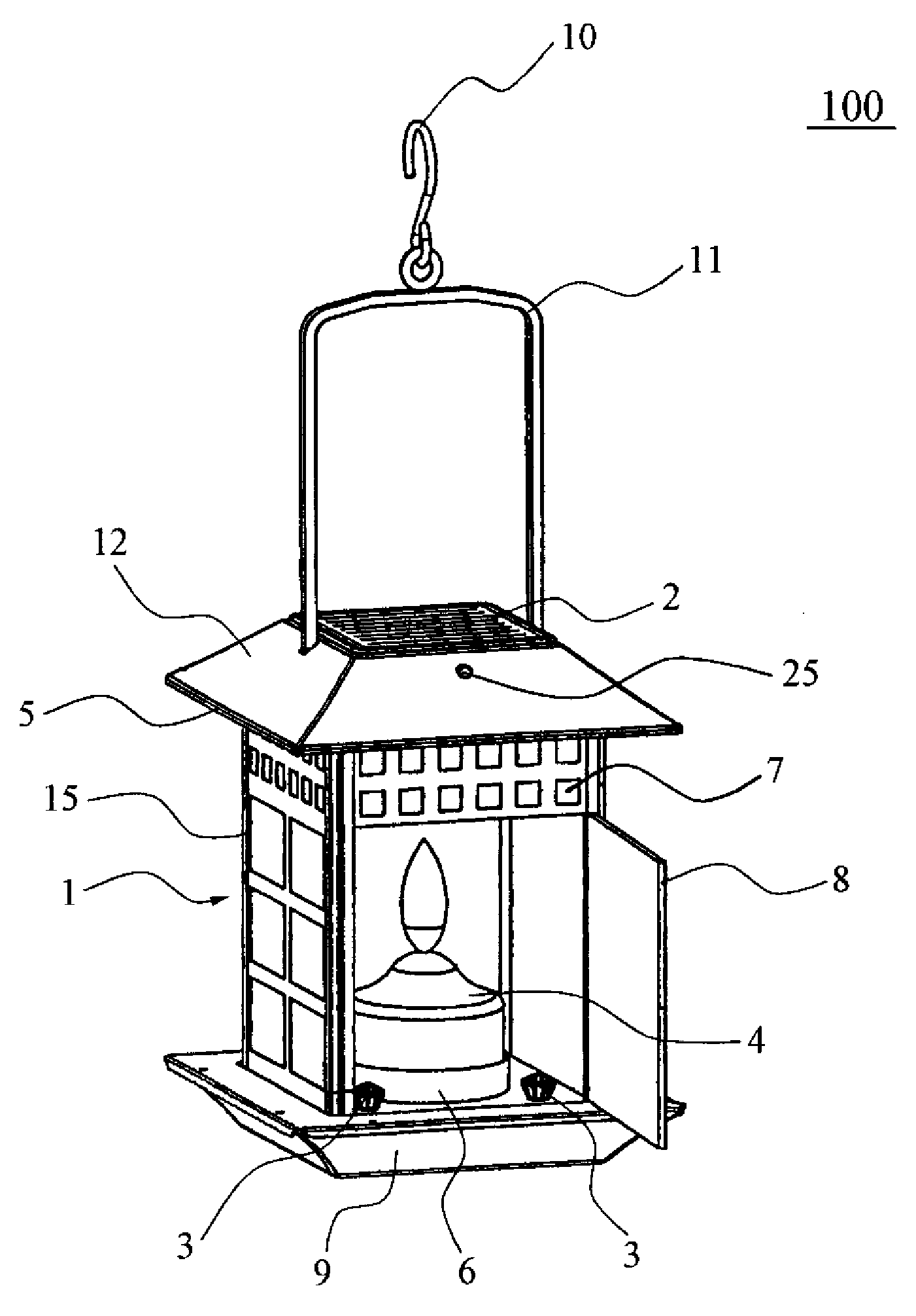
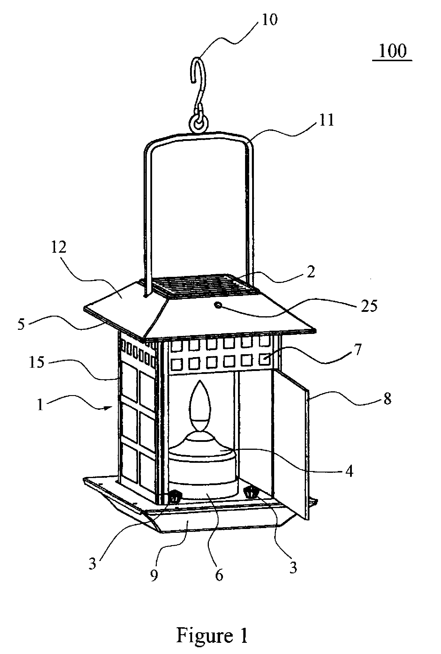
[0015]FIG. 1 illustrates a candle lamp with a solar illumination device according to an embodiment of the present invention. The candle lamp 100 comprises a lamp body 1 that has a lampshade 15 configured in the shape of a quadrangular prism. The lampshade 15 with its lower end portion is mounted on a base 9.

[0016]A plurality of ventilating openings 7 are provided at an upper portion of the lampshade. Each of four side portions of the lampshade is made to be transparent or semi-transparent. One of the side portions is configured to provide a movable door 8.

[0017]A lid 12 having the shape of a truncated pyramid and being connected to and above the lampshade 15 is provided in this embodiment. A heat isolation plate 5 may be provided between the lid and the lampshade to isolate heat generated by the candle 4.

[0018]An inverted U shaped handle 11 is provide to connect the lid 12 by its two ...


PUM


Abstract

Disclosed is a candle lamp a base which comprises a base; a lampshade releasably mounted on the base; a candle holder disposed within the lampshade to hold a candle; a lid disposed above the lampshade; at least one solar power supplier arranged at an outer surface of the lid; and at least one illuminant electrically communicated with the solar power supplier.

Description

CROSS REFERENCE TO RELATED APPLICATIONS[0001]The application claims the benefit of Chinese patent application No. 200620057558.4 filed on Apr. 11, 2006 which is explicitly incorporated by reference in its entirety.BACKGROUND OF THE INVENTION[0002]1. Field of the Invention[0003]This invention relates generally to a candle lamp, and specifically, to a candle lamp with solar illuminating devices.[0004]2. Description of the Prior Art[0005]A conventional solar lamp needs to work in sunlight or at least in sunlight for a while, but would not work in continuous overcast or rainy days accordingly.[0006]A candle lamp has been used for a long time. Currently the candle lamp mainly is used where electrical power is difficult to reach or at specific places that need to be decorated for example. However, the candle lamp is not convenient to use because the candle needs to be lighted manually and replaced frequently.[0007]Thus, there has been a longstanding need to provide a lamp that combines a ...

Claims


Application Information

Patent Timeline
IPC IPC(8): F21L4/00F21Y113/20
CPCF21S9/037
Inventor FAN, QUANWEI
Owner GUANGZHOU FAPU ELECTRONICS & TECH
Learn More