
Method of reducing a peak to average power ratio of a modulated signal

a modulated signal and average power technology, applied in the direction of transmission path sub-channel allocation, multi-frequency code system, transmission path division, etc., can solve problems such as hammering practical implementations, and achieve the effect of reducing the peak to average power ratio, spectral efficiency and the range of the broadband wireless access system employing the method in accordance with the invention

Inactive Publication Date: 2007-10-11
WI LAN INC
View PDF2 Cites 6 Cited by
  • Summary
  • Abstract
  • Description
  • Claims
  • Application Information

AI Technical Summary

Benefits of technology

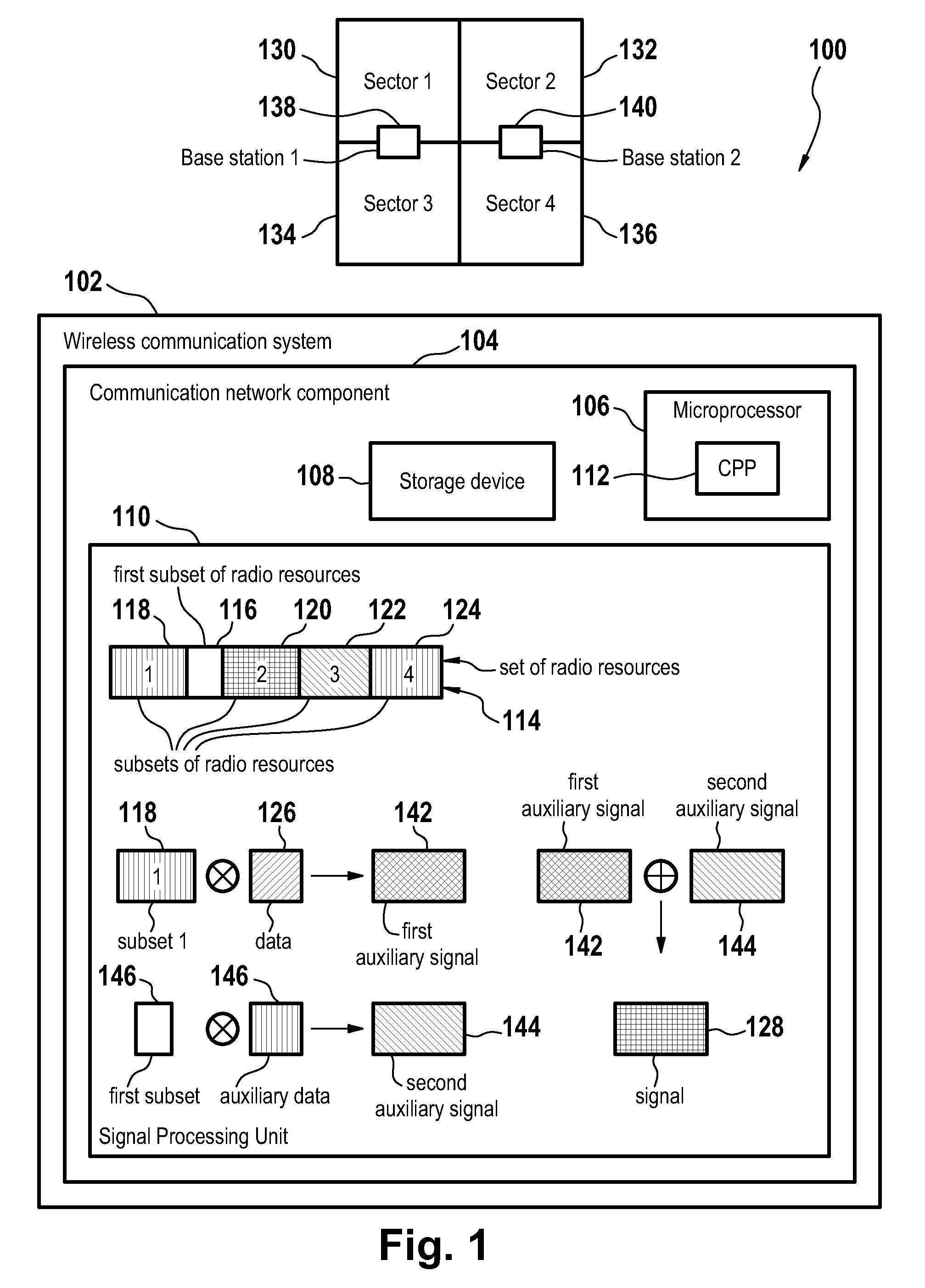
[0013]As mentioned, a first subset of radio resources is selected from the given set of radio resources and is employed for a reduction of the peak to average power ratio of all signals to be transmitted. In principle, a part of each subset of radio resources could be used for a reduction of the peak to average power ratio of signals that are generated by use of the corresponding subset of radio resources. However, the selection of a first subset of radio resources which is then employed for a peak to average power ratio of all signals that are to be transmitted leads typically to a reduction in the number of radio resources that are reserved for a peak to average power ratio reduction. Hence, more radio resources are available for the delivery of data. Thus the spectral efficiency and the range of the broadband wireless access system employing the method in accordance with the invention is enhanced.

Problems solved by technology

The occurrence of these peaks seriously hampers practical implementations due to for example peak power limitations in the signal processing chain and is generally considered as one of the major drawbacks of the employment of modulation techniques such as OFDM.

Method used


Image

  • Method of reducing a peak to average power ratio of a modulated signal
  • Method of reducing a peak to average power ratio of a modulated signal
  • Method of reducing a peak to average power ratio of a modulated signal

Examples


Embodiment Construction

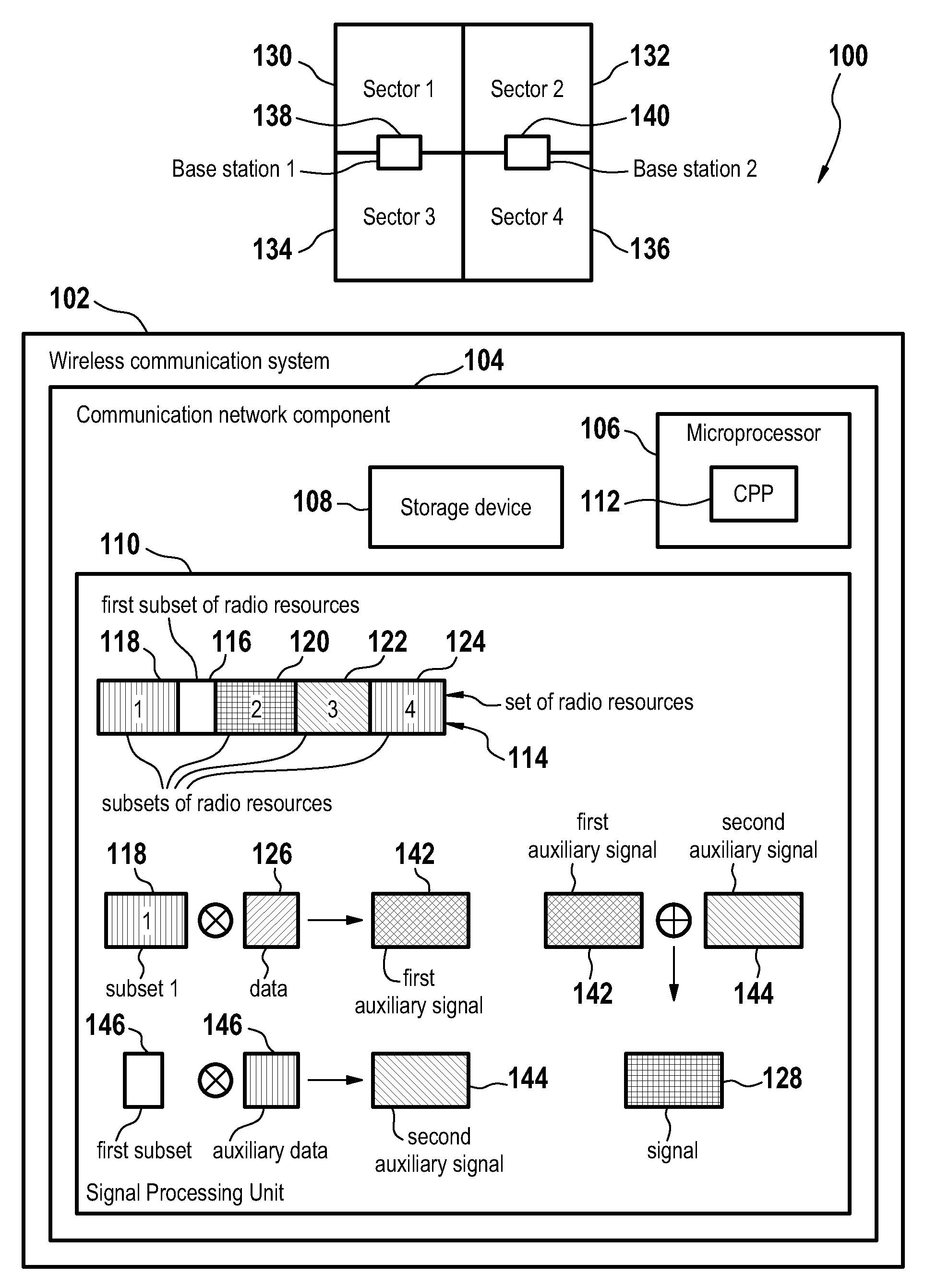
[0045]FIG. 1 is a block diagram 100 showing schematically a wireless communication system 102 serving a plurality of sectors consisting of sector 1130, sector 2132, sector 3134, and sector 4136, whereby a signal which is designated for sector 1130 or sector 3134 is transmitted by base station 1138, and whereby a signal which is designated for sector 2132 or sector 4136 is transmitted by base station 2140. The base stations 138 and 140 are comprised in the wireless communication systems 102.

[0046]The wireless communication system 102 further comprises a communication network component 104. The communication network component 104 comprises a microprocessor 106, a storage device 108, and a signal processing unit 110. The signal processing unit 110 provides a set of radio resources 114.

[0047]The microprocessor 106 executes a computer program product 112 which is loaded from the storage device 108 for example during the startup of the communication network component 104. The computer pro...


PUM


Abstract

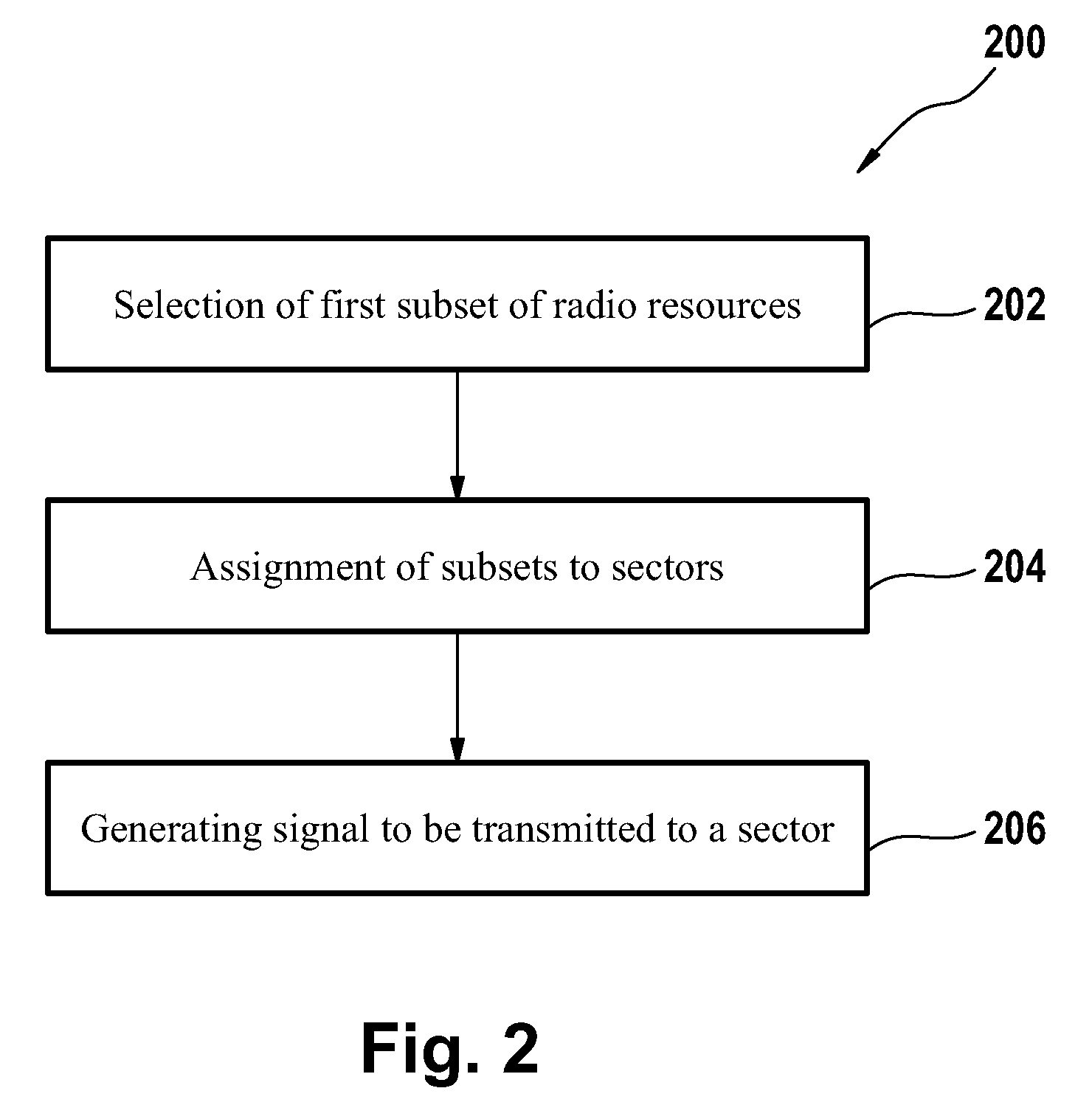
The invention relates to a method of reducing a peak to average power ratio of a signal, wherein the signal comprises data that is designated for transmission to a sector of a plurality of sectors, and wherein the method comprises the steps of selecting a first subset of radio resources from a given set of radio resources and of assigning a subset of radio resources from the remaining set of radio resource to each sector of said plurality of sectors. Each subset of radio resources is at least approximately disjoint from another subset of radio resources. The method in accordance with the invention further comprises the step of generating the signal by combining the data on the subset of radio resources that has been assigned previously to the sector and by employing said first subset of radio resources for a reduction of the peak to average power ratio. In another aspect the invention relates to a communication network component, to a computer program product and to a wireless communication system.

Description

[0001]The invention is based on a priority application EP 06290615.1 which is hereby incorporated by reference.TECHNICAL FIELD[0002]The invention relates to a method of reducing a peak to average power ratio of a modulated signal designated for transmission to a sector of a plurality of sectors in general.BACKGROUND OF THE INVENTION[0003]Modulation techniques are commonly employed for transmitting signals in various communication systems. For example, orthogonal frequency division multiplexing (OFDM) has found its way to the high-speed wireless and mobile communication arena. It has been standardized for digital audio broadcast (DAB) in Europe, enabling the mobile reception of high-quality digital audio combined with data services. OFDM has also been adopted for wireless metropolitan and local area networks (WMANs and WLANs) to satisfy the high bit rate requirements of multimedia services and is officially included in the IEEE 802.11 and the IEEE 802.16 (WIMAX) standard.[0004]In an ...

Claims


Application Information

Patent Timeline
Patent Type & Authority Applications(United States)
IPC IPC(8): H04K1/10
CPCH04L5/0007H04L27/2618H04L5/0046H04L5/0032
Inventor SCHAEPPERLE, JOERGOTTERBACH, JURGEN
Owner WI LAN INC
Learn More