Multilayer load bearing structure

a load-bearing structure and multi-layer technology, applied in the direction of shock absorption devices, chairs, furniture parts, etc., can solve the problems of not always providing the appropriate level of support for each part of the body, and people spend a significant number of hours sitting each day

Active Publication Date: 2007-10-25
MILLERKNOLL INC
View PDF99 Cites 22 Cited by
  • Summary
  • Abstract
  • Description
  • Claims
  • Application Information

AI Technical Summary

Benefits of technology

[0007] Structural components consistent with the present invention provide pixelated body support elements as well as pixelated body support structures incorporating the pixelated body support elements. The support structures may be employed in the design of a backrest or seat for a chair, as examples, or may be incorporated into any other body support device (e.g., a mattress or bed system). The pixelated support elements may be independently designed according to their selected or assigned location in the support structure. The resultant design may thereby provide point-tailored support for the body that varies according to support most beneficial or desirable for any given body region.
[0010] Similarly, a pixelated support structure consistent with the present invention may include a support spine, a spline disposed laterally across the support spine, and cantilever branches extending outwardly from the spline. Each cantilever branch may include a terminal end connected to the spline, a support end opposite the terminal end, and a load bearing element connected to the support end. Additionally, a bridging connection is provided between pixelated support elements, thereby connecting sets of load bearing elements together into larger groups (e.g., a 2×2 or 4×4 group of load bearing elements). The bridging connection between elements prevents neighboring support elements from pinching the body between them as they flex differentially.

Problems solved by technology

People spend a significant number of hours sitting each day.
These past designs have been successful to varying degrees, but do not always provide the appropriate level of support for each part of the body.

Method used


Image

  • Multilayer load bearing structure
  • Multilayer load bearing structure
  • Multilayer load bearing structure

Examples


Embodiment Construction

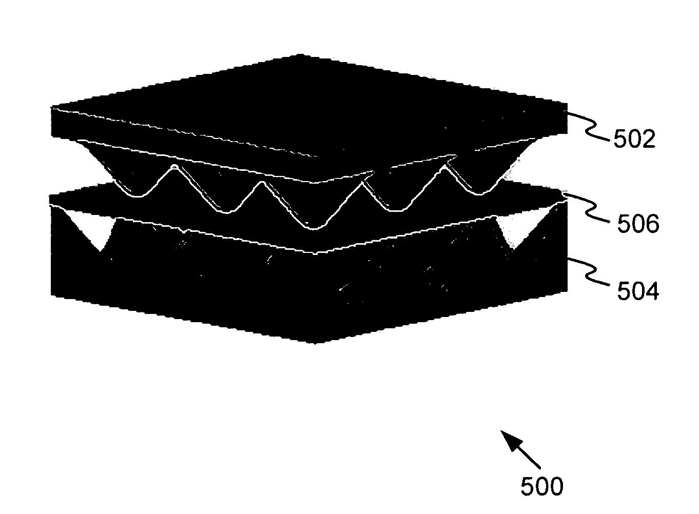
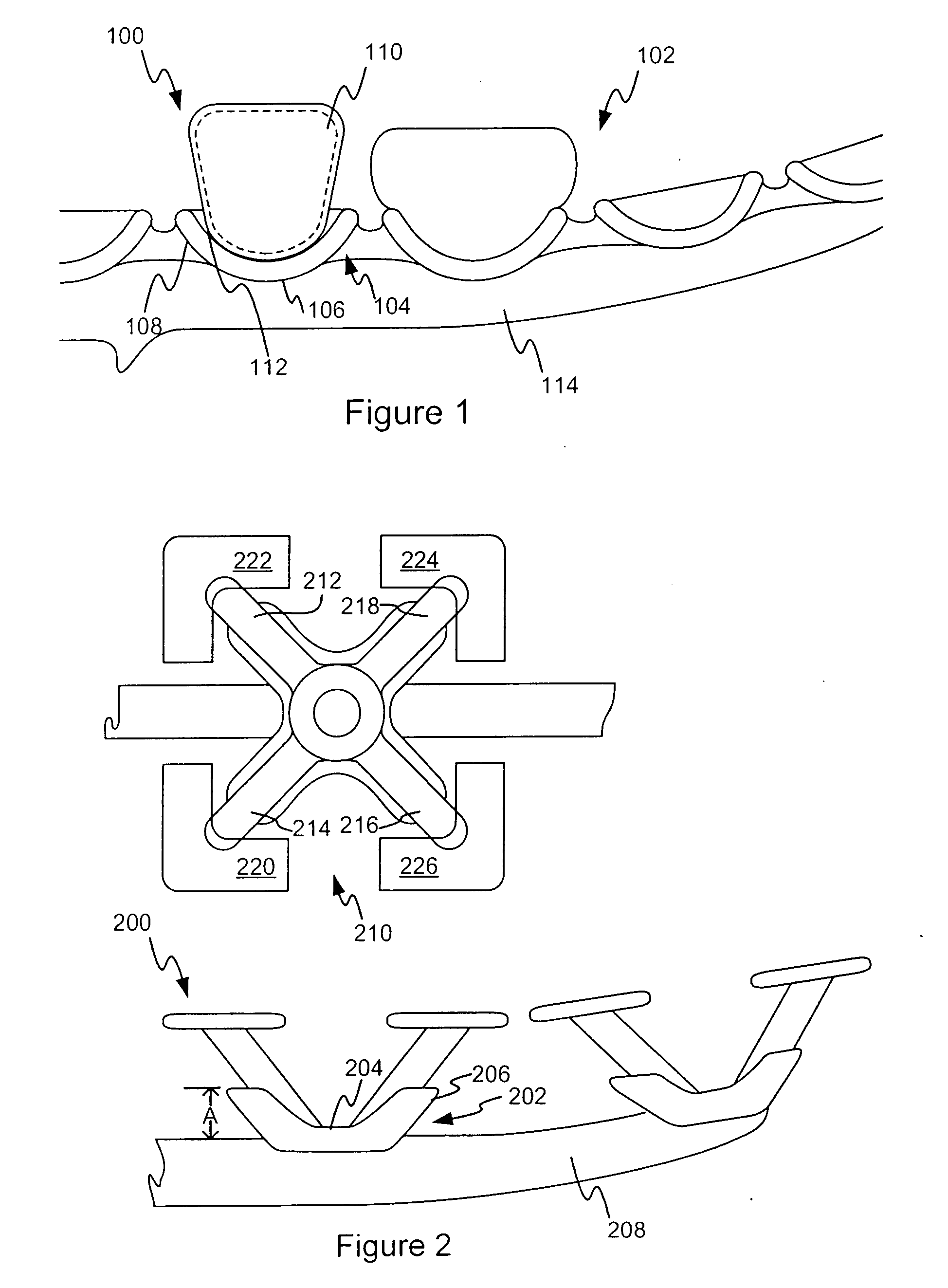
[0075] Before turning to a detailed discussion of the Figures, it is noted that pixelated body support generally refers to an array of individual body-support elements that in combination provide support for some or all of an individual's body. For example, the body support may include an array of closely spaced pixelated support elements that define a support surface for an individual. As will be explained in more detail below, the pixelated support elements may take many forms, including, for example a spring-loaded element formed as, or biased by, mechanical or pneumatic springs or by other devices. Furthermore, the stiffness or biasing force of the pixelated support elements may be individually designed as desired to suit the particular body support needs of the individual and the application.

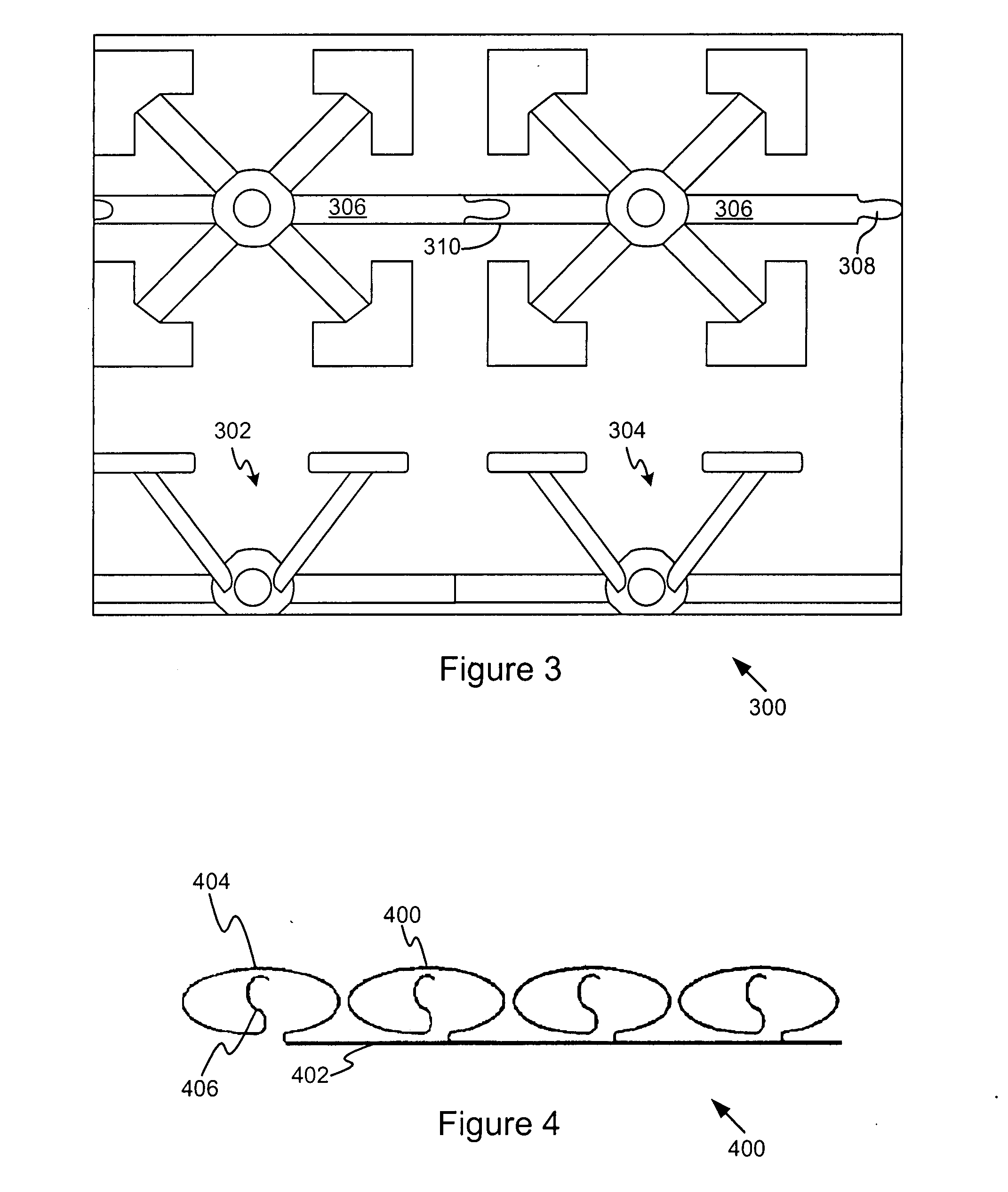
[0076] Several exemplary implementations of pixelated support elements (referred to below as “elements” or “support elements”) are discussed next. Subsequently, pixelated support structure...


PUM

PropertyMeasurementUnit
distancesaaaaaaaaaa
depthsaaaaaaaaaa
separation distancesaaaaaaaaaa

Abstract

Support elements and support structures form the basis of ergonomic body supports for chairs, mattresses and other structures. The support elements may be individually designed according to their location and body support function. Thus, the structures that include the support elements may provide point-tailored support for any part of the body to enhance comfort, fit, and proper anatomical support.

Description

PRIORITY CLAIM [0001] This application is a Continuation application of U.S. patent application Ser. No. 10 / 972,153, titled PIXELATED SUPPORT STRUCTURES AND ELEMENTS, filed Oct. 22, 2004 and further claims the priority benefit of both U.S. Provisional Patent Application No. 60 / 513,775, titled PIXELATED SUPPORT STRUCTURES AND ELEMENTS, filed Oct. 23, 2003, and U.S. Provisional Patent Application No. 60 / 599,201, titled PIXELATED SUPPORT STRUCTURES AND ELEMENTS, filed Aug. 5, 2004.BACKGROUND [0002] 1. Technical Field [0003] The present invention relates to load bearing structures. In particular, the present invention relates to multiple layer load bearing structures. [0004] 2. Background Information [0005] People spend a significant number of hours sitting each day. Regardless of the task being performed, or the leisure activity being pursued, support structures that properly support the body not only make the individual more comfortable, but may also provide significant health benefit...

Claims


Application Information

Patent Timeline
Patent Type & Authority Applications(United States)
IPC IPC(8): A47C27/00A47CA47C7/02A47C7/24A47C23/00A47C23/05
CPCA47C7/022A47C7/027F16F1/025A47C23/002A47C23/05A47C7/282A47C7/029A47C7/144A47C7/24A47C7/28A47C7/30A47C7/34A47C23/04A47C23/06A47C23/12F16F1/02F16F1/12A47C7/26F16F1/36
Inventor VANDERIET, DOUGLAS M.HILL, CHIRSTOPHER C.KURRASCH, ANDREW J.ALDRICH, JOHN F.HOOGLAND, TIMOTHYWEBER, JEFFREY A.HOLT, JASONBRILL, RYAN S.
Owner MILLERKNOLL INC
Why Eureka
Try Eureka