Eureka AIR delivers breakthrough ideas for toughest innovation challenges, trusted by R&D personnel around the world.

Paddle latch

Active Publication Date: 2007-11-01
WESTON BODY HARDWARE
View PDF9 Cites 5 Cited by
  • Summary
  • Abstract
  • Description
  • Claims
  • Application Information

AI Technical Summary

Benefits of technology

[0014] As discussed, known latches often comprise shafts on which the paddle rotates, but the interaction between the paddle and the latch member is normally a direct one giving rise to the necessity for large slots or orifices, which can cause water ingress into the container or building. The present invention overcomes this by allowing the drive shaft to transfer the force between the paddle and the latch member such that the only orifices that are required in the paddle latch are those through which the drive shaft must pass. This is advantageous as the drive shaft motion is only rotational and therefore orifices with a tight fit can be used, which may be more resistant to water ingress than prior art latches whilst still providing the required functionality.

Problems solved by technology

As discussed, known latches often comprise shafts on which the paddle rotates, but the interaction between the paddle and the latch member is normally a direct one giving rise to the necessity for large slots or orifices, which can cause water ingress into the container or building.
Large slots of orifices can transmit noise from the interior to the exterior of the container, which is undesirable (as discussed above).

Method used


Image

  • Paddle latch
  • Paddle latch
  • Paddle latch

Examples


Embodiment Construction

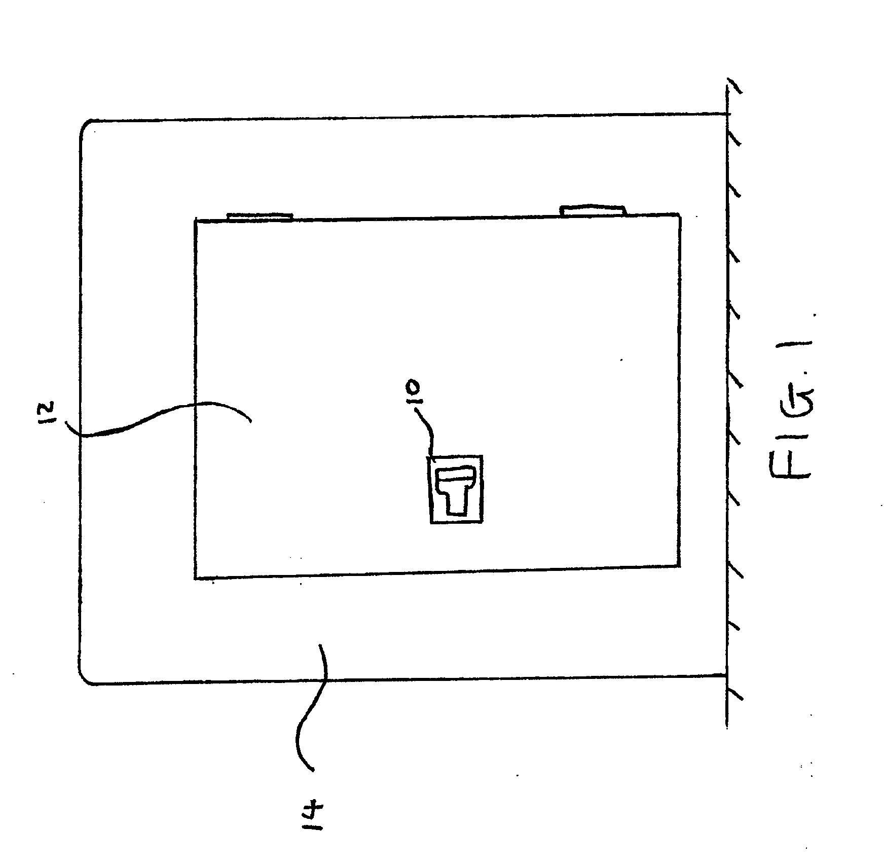
[0033] Referring to FIG. 1 a paddle latch 10 is configured for use with a door 12 on a container 14.

[0034] The container 14 comprises a striker 15 (as shown in FIG. 3) with which the panel latch 10 interacts in order to secure the door 12 in a closed position. The striker 15 may take many forms but is generally a metal member or bar attached to the container 14, or simply a portion of the door surround of the container.

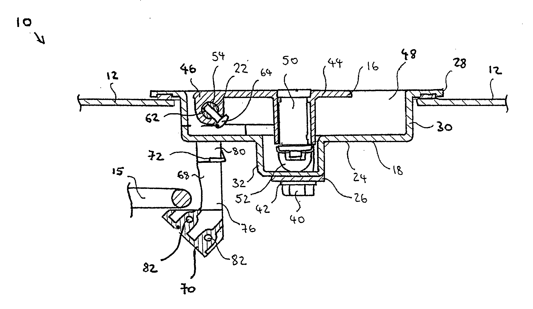
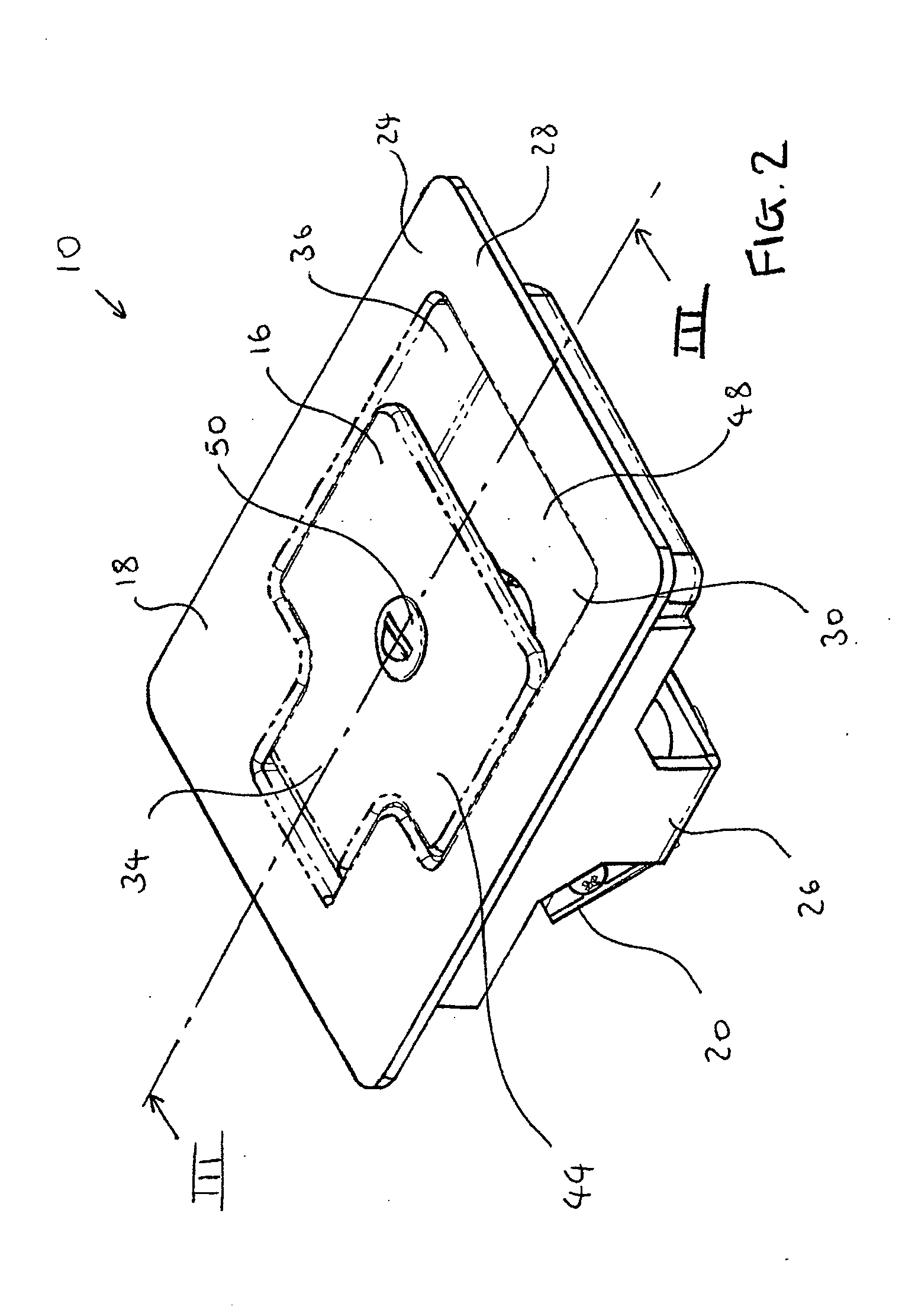
[0035] Referring to FIGS. 2 to 6, paddle latch 10 comprises a handle, commonly referred to as a paddle 16, housing 18, latch member 20 and drive shaft 22.

[0036] The housing 18 comprises a housing body 24 and an attachment bracket 26 as depicted in FIG. 4.

[0037] The housing body 24 is a moulded plastic or stamped metal component comprising a substantially flat flanged portion 28, a first depression 30 and a further depression 32 formed therein. The first depression 30 comprises a small rectangular section 34 and an adjacent large rectangular section 36. The small r...


PUM


Abstract

A paddle latch comprising a housing defining a first side and a second side, a shaft extending through the housing defining a first shaft portion on the first side and a second shaft portion on the second side, a paddle for actuation by a latch user on the first side and a releasable latch member for co-operation with an associated striker to latch the paddle latch on the second side wherein the paddle is connected to the first shaft portion and the latch member is connected to the second shaft portion such that torque may be transferred from the paddle to the latch member to release the latch member from the striker in use.

Description

REFERENCE TO RELATED APPLICATIONS [0001] This application claims priority to United Kingdom Patent Application 0606631.0 filed on Apr. 1, 2006, the entirety of which is incorporated by reference herein. BACKGROUND TO THE INVENTION [0002] The present invention relates to a paddle latch for a closure. Particularly, although not exclusively, the present invention concerns paddle latches designed to be installed on the doors of heavy plant containers and buildings where water ingress to the interior of the container or building is undesirable. [0003] It is known to provide paddle latches on the doors of heavy plant containers or buildings containing heavy plant equipment such as generators or pumps. Paddle latches are suited to this application as paddles generally provide a large area with which to actuate the latch, which can be advantageous if the user is wearing protective gloves. Furthermore, the paddle latch acts as a latch and handle whereby the user only needs to pull on the pad...

Claims


Application Information

Patent Timeline
IPC IPC(8): E05C1/12
CPCE05C3/162Y10T292/0994Y10T70/5761E05C3/122
Inventor WOLLACOTT, MARTINDOWNING, MATTHEW
Owner WESTON BODY HARDWARE
Why Eureka
Eureka Blog
Learn More