
Camera-Equipped Cellular Terminal for Visible Light Communication

a cellular terminal and camera technology, applied in the field of camera-equipped cellular terminals, can solve the problems of limited information transfer speed for visible light communication, excessive specification of camera functions, and high cos

Inactive Publication Date: 2007-11-01
NAKAGAWA LAB INC
View PDF2 Cites 110 Cited by
  • Summary
  • Abstract
  • Description
  • Claims
  • Application Information

AI Technical Summary

Benefits of technology

[0012] Provision of the light receiving unit for visible light communication in addition to the camera allows high-speed reception of information through the visible light communication without any constraints for the camera.
[0013] Furthermore, when the camera is used as a finder to display, the light receiving unit may receive information through the visible light communication.

Problems solved by technology

This is an excessive specification as camera's functions and is thus expensive.
When using a typical camera for visible light communication, information transfer speed for visible light communication is limited due to a low-speed sampling frequency.

Method used


Image

  • Camera-Equipped Cellular Terminal for Visible Light Communication
  • Camera-Equipped Cellular Terminal for Visible Light Communication
  • Camera-Equipped Cellular Terminal for Visible Light Communication

Examples


Embodiment Construction

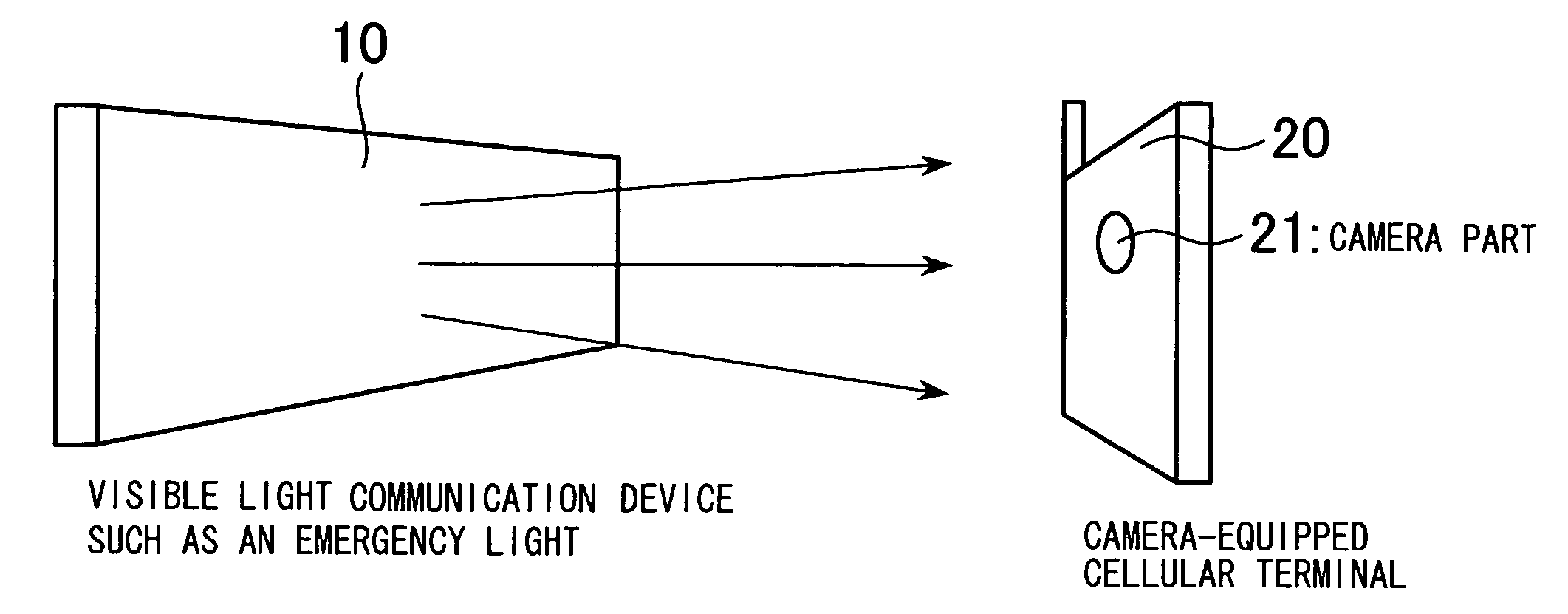
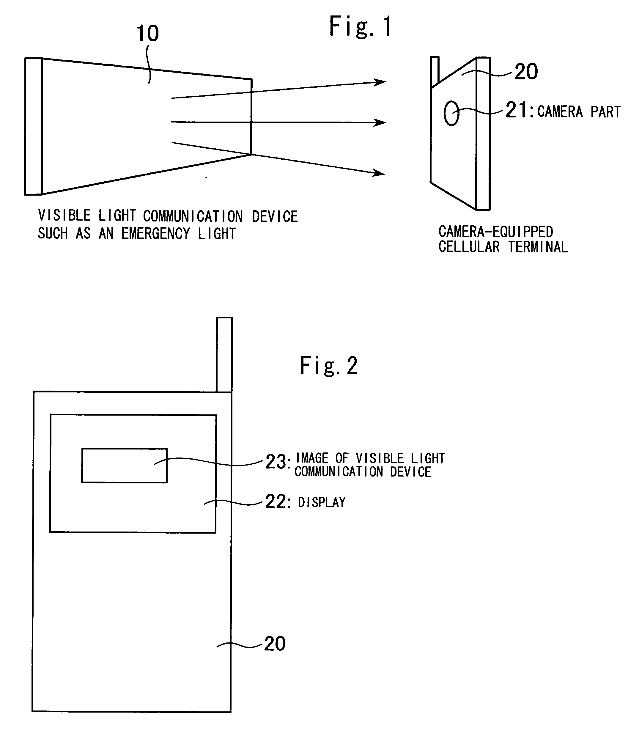
[0018] An embodiment of the present invention is described using the appended drawings.

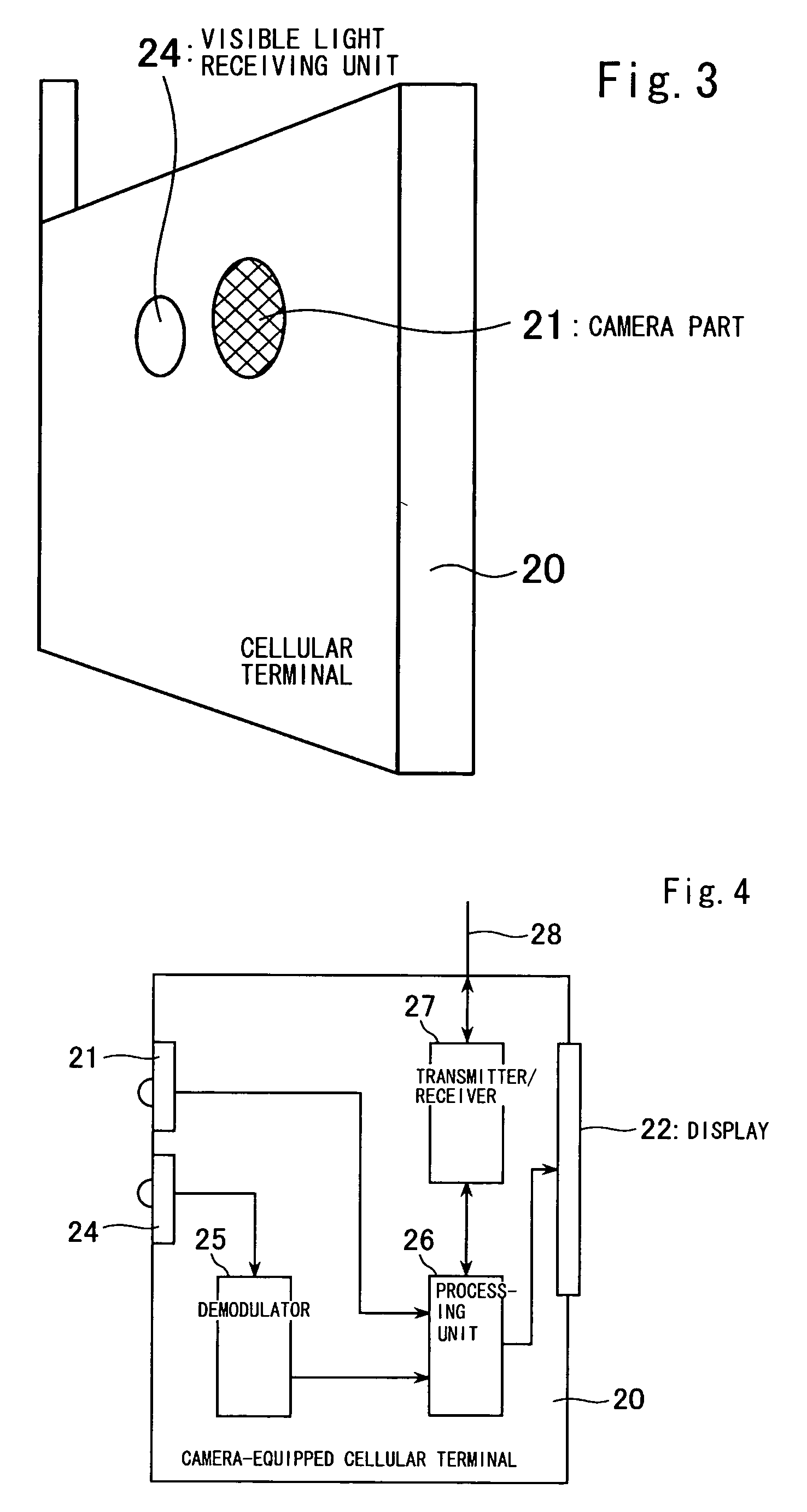
[0019]FIGS. 3 and 4 show the embodiment of the present invention.

[0020] As shown in FIG. 3, in order to receive information from visible light (including illuminative light) separate from a camera 21 of a conventional camera-equipped cellular terminal 20, a visible light receiving unit 24 pointing in the same direction as a light receiving lens of the camera 21 is provided. This light receiving unit 24 receives visible light information. This light receiving unit 24 may be configured by a photodiode or the like.

[0021]FIG. 4 is a block diagram showing a function of the camera-equipped cellular terminal 20 of FIG. 3. In FIG. 4, an image taken by the camera 21 is processed by a processing unit 26 and then displayed on a display 22. Information from a visible light communication device (e.g., an illuminating device such as an emergency light) is converted to an electronic signal by the light receiv...


PUM


Abstract

The present invention provides a camera-equipped cellular terminal capable of receiving visible light communication. In order to receive information from visible light, a light receiving unit (24) for visible light pointing to the same direction as a light receiving lens of the camera (21) is provided other than a camera (21) of a conventional camera-equipped cellular terminal (20). This light receiving unit (24) receives information from the visible light. This light receiving unit (24) may be configured by a photodiode or the like. When the camera (21) is used as a finder to display an illuminating device conducting visible light communication in a display of the camera, whether the light receiving unit 24 can receive information through visible light communication is determined.

Description

TECHNICAL FIELD [0001] The present invention relates to a camera-equipped cellular terminal configured to receive visible light communication. BACKGROUND ART [0002] Cellular phones are a key element supporting Japan's industries today. 70 million cellular phone units are being used in Japan. The cellular phone terminal does not only function as a telephone, but includes an infrared data reader and a camera to take pictures, and may even recognize images. Furthermore, having an RF-ID tag is becoming more frequent. Possession of a cellular terminal is equivalent to having a credit card, and even an identification card in some cases. The cellular terminal takes the market position of personal computers of the 1990s. In this state, cameras have a function of receiving external visible images and are widely prevalent. A system including a cellular terminal, which extracts information from a communication device (e.g., a communication device configured to modulate at a high speed an LED u...

Claims


Application Information

Patent Timeline
IPC IPC(8): H04M1/00H04M1/02G06F1/16H04B7/26H04B10/11H04B10/112H04M1/21H04M1/72412H04W88/02
CPCG06F1/1626G06F1/1686H04B10/1141H04B10/1143H04M2250/52H04B10/22H04M1/72527H04M2250/12H04B10/116H04M1/72412H04B1/40H04M1/02H04M1/21
Inventor NAKAGWA, MASAOHARUYAMA, SHINICHIRO
Owner NAKAGAWA LAB INC
Learn More