Flat heating element

a technology for heating elements and flats, applied in the field of flat heating elements, can solve the problems of very little possibility of a contact conductor to yield to a load, and achieve the effects of increasing the probability of a fractured contact conductor strand, significantly increasing the probability of fracture, and high failure probability

Inactive Publication Date: 2007-11-08
GENTHERM GMBH
View PDF5 Cites 16 Cited by
  • Summary
  • Abstract
  • Description
  • Claims
  • Application Information

AI Technical Summary

Benefits of technology

[0006]A detailed evaluation of contact conductor strand fractures has shown that the probability of fractures is significantly higher at the extreme values of its progression, or at its peaks, than in the remaining regions. The reason for this can be seen in that they extend approximately parallel to the contacting region or to an electrode in the region of such extreme values. Consequently, a contact conductor has very little possibility of yielding to a load. A heating element according to Claim 1 avoids the zones of higher failure probability of different contact conductor strands from being arranged directly adjacent to one another. This significantly increases the probability of a fractured contact conductor strand being bridged by adjacent contact conductor strands, and thus ensures conductivity along the contacting region. It is particularly advantageous if the majority of locations that, at least locally, extend parallel to the electrode are provided with another contact conductor strand that, at least locally, extends in a non-parallel fashion. It is advantageous if at least one-half of the remaining contact conductor strands are suitable for this type of bridging, preferably at least 70%, particularly 90%.
[0007]Heating elements according to Claims 2 and 3 can be efficiently produced with respect to the manufacturing technology.

Problems solved by technology

Consequently, a contact conductor has very little possibility of yielding to a load.

Method used


Image

  • Flat heating element
  • Flat heating element
  • Flat heating element

Examples


Embodiment Construction

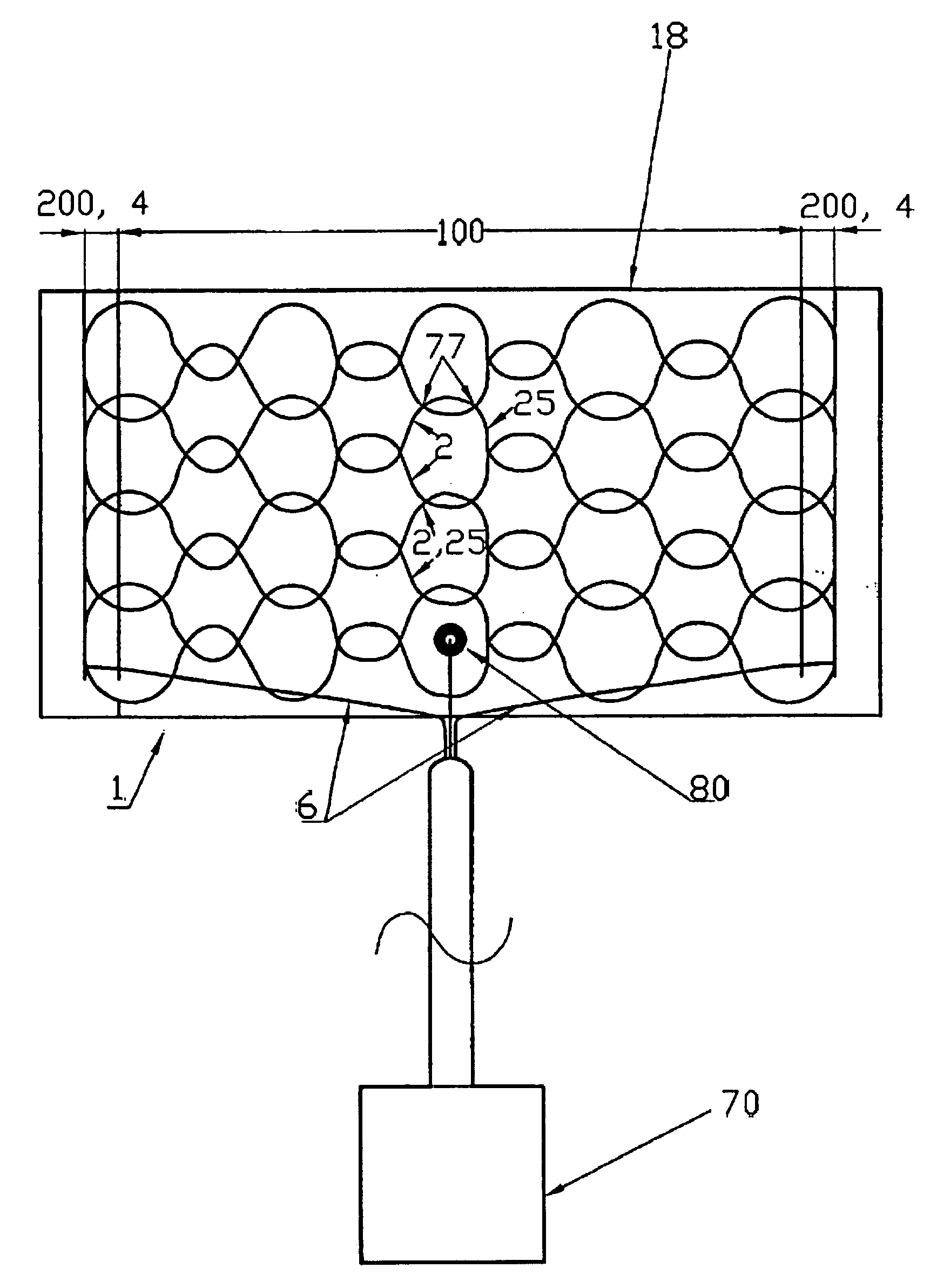
[0021]FIG. 1 shows a flat electric heating element 1 (“heating element 1”).

[0022]The heating element 1 features at least one flat heating resistor (18) (“heating resistor 18”).

[0023]It features at least one flat carrier 8 (“flat carrier 8”). It may be appropriate for at least one of the carriers 8 to consist at least partly of a textile, knitted fabric, woven fabric, nonwoven fabric, flexible thermoplastic, air-permeable material and / or foil. In the embodiment shown a carrier 8 is provided with a non-woven fabric made of man-made fibers.

[0024]According to the invention, the heating element 1 features at least one heating zone 100 (“heating zone 100”). This heating zone is associated with or forms a surface to be heated. It is largely identical to the heating resistor 18.

[0025]The heating resistor 18 features, in particular, at least one heating conductor 2 (“heating conductor 2”) that is arranged on and / or in the heating zone 100. It is preferred to configure a plurality of heating ...


PUM


Abstract

The present invention pertains to an electric heating element with at least one flat heating resistor to be arranged near a surface to be heated, and at least one electrode that serves to feed a current into the heating resistor and features at least two contact conductor strands that are, at least locally, connected to one another and to the heating resistor, at least in an elongated contacting region. The invention proposes that at least at one location along the electrode and/or the contacting region at which at least one of the contact conductor strands, at least locally, extends parallel to the direction of the electrode, and/or the contacting region, at least one additional contact conductor strand, at least locally, extends at an angle thereto.

Description

CLAIM OF BENEFIT OF EARLIER FILING DATE[0001]The present application claims the benefit of the filing date of German Application Nos. DE 102006021649.0 (filed May 8, 2006) the contents of which are hereby incorporated by reference in their entirety.TECHNICAL FIELD[0002]The present invention pertains to flat heating elements, particularly for user-contacted heating surfaces in the passenger compartment of a vehicle, to seats, particularly for vehicles, as well as to vehicles, according to the preambles of the independent claims.BACKGROUND OF THE INVENTION[0003]Electric heating elements in which a flat heating resistor is electrically contacted on respectively opposite sides by contact conductors, are known from DE 4101290 C2 and from EP 0939579 B1. In order to produce as many contact points as possible between the heating resistor and the contact conductors and to stabilize the contact conductors with respect to mechanical stresses, the heating conductors are arranged at the heating ...

Claims


Application Information

Patent Timeline
Patent Type & Authority Applications(United States)
IPC IPC(8): H05B3/54
CPCH05B3/34H05B2203/003H05B2203/005H05B2203/029H05B2203/014H05B2203/017H05B2203/011
Inventor KROBOK, MARTIN
Owner GENTHERM GMBH
Why Eureka
Try Eureka