System for optimal alignment of a bearing seal on a shaft of a gas turbine

a technology for gas turbine shafts and bearing seals, applied in the field of gas turbines, can solve the problems of relative rapid wear and early onset of oil leakage of seal structures

Inactive Publication Date: 2007-11-08
AXIAM
View PDF17 Cites 18 Cited by
  • Summary
  • Abstract
  • Description
  • Claims
  • Application Information

AI Technical Summary

Problems solved by technology

However, the high speed shaft rotation and other operating conditions in a gas turbine environment have generally precluded complete elimination of the oil leakage.
That is, high speed shaft rotation tends to result in relatively rapid wear of seal structures and early onset of oil leakage.
This problem is compounded by high temperature operating environments and adverse differential pressures which may be present on opposite sides of the bearing housing end wall.

Method used


Image

  • System for optimal alignment of a bearing seal on a shaft of a gas turbine
  • System for optimal alignment of a bearing seal on a shaft of a gas turbine
  • System for optimal alignment of a bearing seal on a shaft of a gas turbine

Examples


Embodiment Construction

[0024] A description of preferred embodiments of the invention follows.

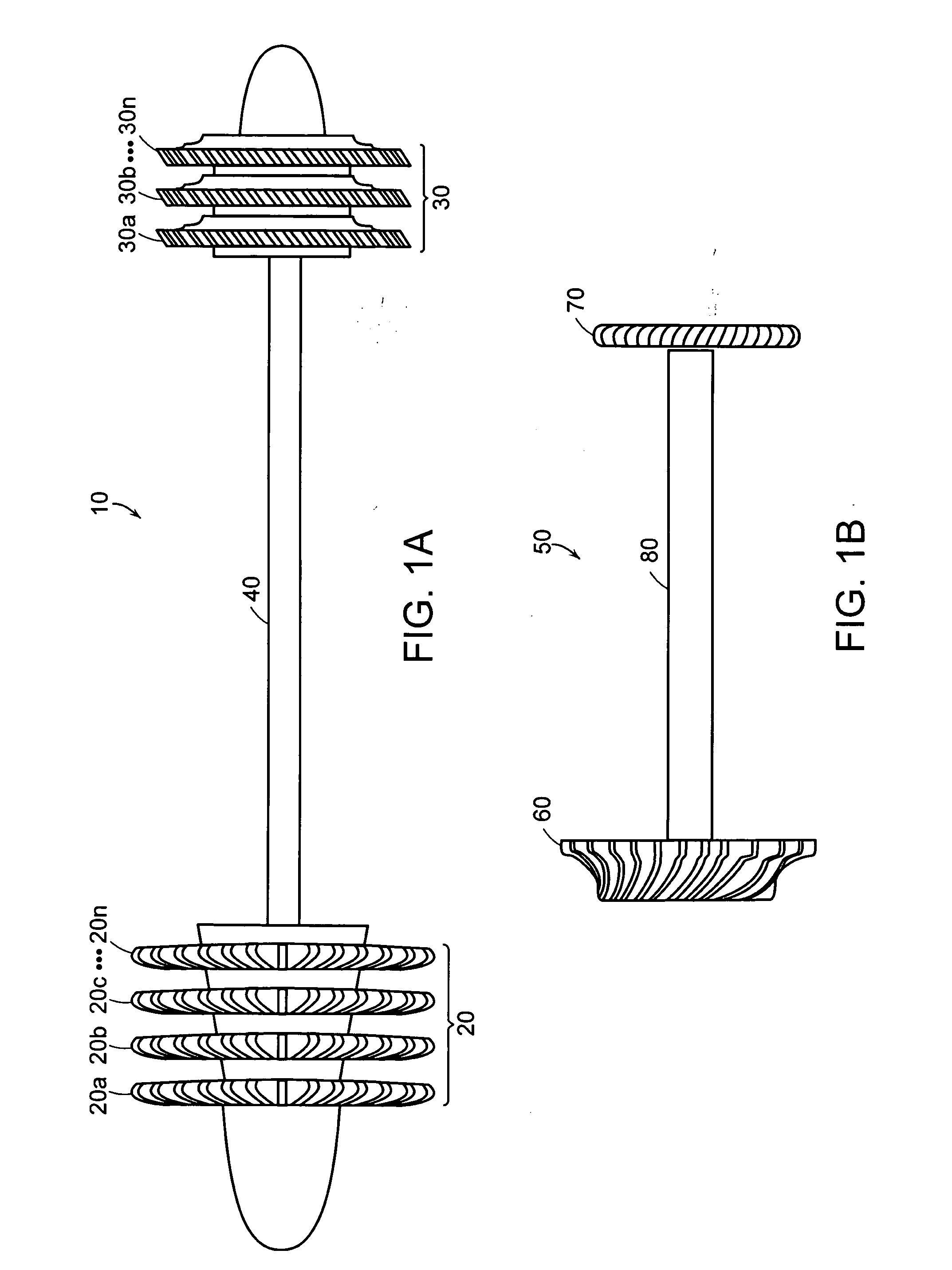
[0025]FIG. 1A shows a low-pressure spool 10 of a gas turbine. The low-pressure spool 10 includes a low-pressure compressor 20, a low-pressure turbine 30, and a low-pressure shaft 40. The low-pressure compressor 20 includes a plurality of discs 20a . . . 20n. The low-pressure turbine 30 includes a plurality of discs 30a . . . 30n.

[0026]FIG. 1B shows a high-pressure spool 50 of a gas turbine. The high-pressure spool 50 includes a high-pressure compressor 60, a high-pressure turbine 70, and a high-pressure shaft 80. The high pressure shaft 80 rotates about the low-pressure shaft 40. In some engine designs, the low-pressure shaft 40 and the high-pressure shaft 80 are the same shaft.

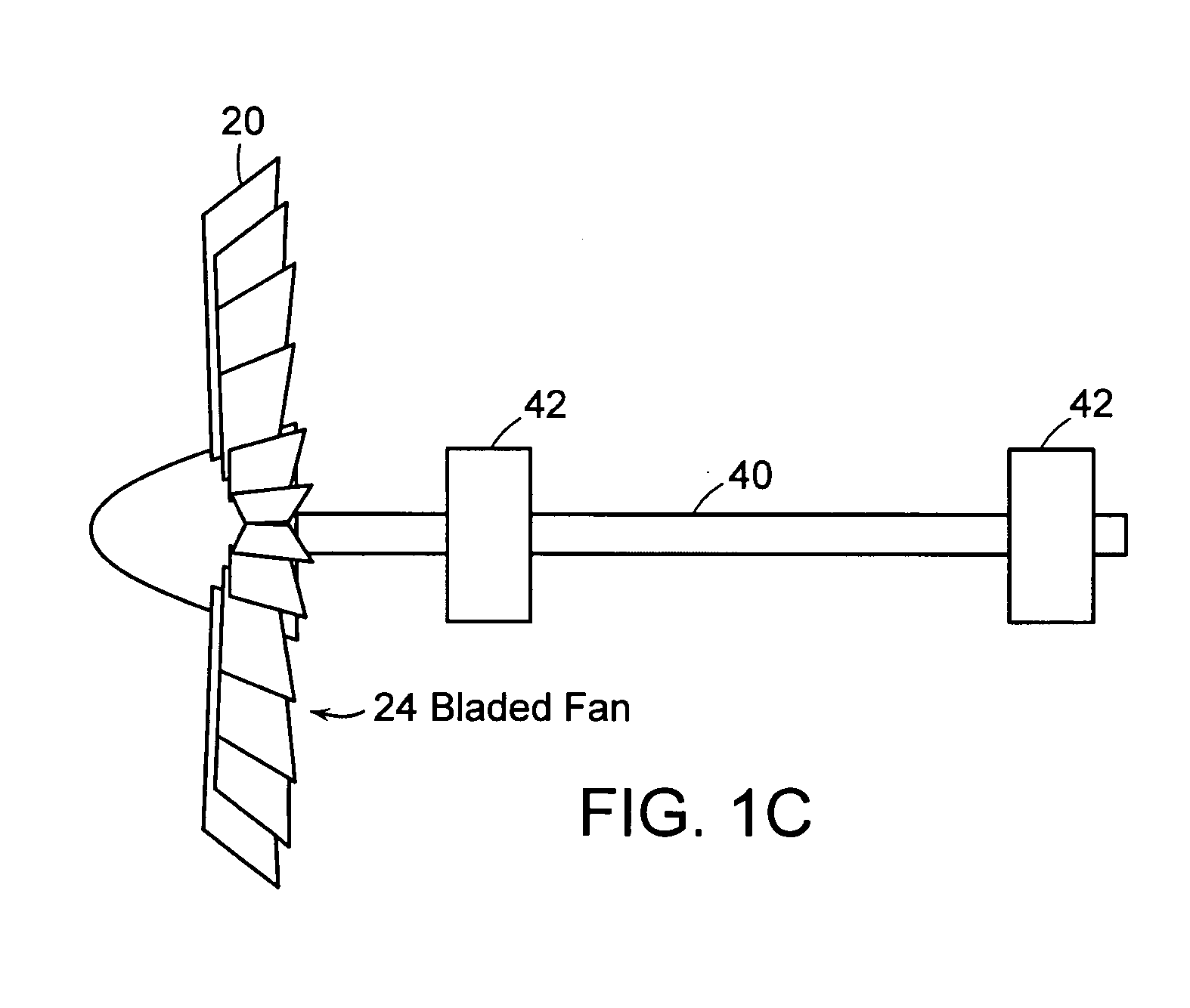
[0027]FIG. 1C generally shows the a low-pressure shaft 40 extending through a pair of bearing housings 42. An oil circulation system delivers lubricating oil to lubricate the bearings (not shown) within the respective bearing housings 4...


PUM


Abstract

A method for substantially aligning a bearing seal on a shaft of a turbine engine. The method including measuring characteristics of the subject shaft, measuring characteristics of a plurality of bearing seal components and determining and outputting alignment information of the plurality of bearing seal components with the shaft based on the measured characteristics. The alignment information can be outputted for either substantially perpendicular alignment for an axial seal or substantially parallel alignment for a radial seal.

Description

RELATED APPLICATIONS [0001] This application is a continuation-in-part of U.S. application Ser. No. 11 / 179,339, filed on Jul. 12, 2005, which is a continuation-in-part of U.S. application Ser. No. 11 / 090,963, filed Mar. 25, 2005, which is a continuation of U.S. application Ser. No. 09 / 950,942, filed on Sep. 11, 2001, now U.S. Pat. No. 6,898,547, issued on May 24, 2005, which claims the benefit of U.S. Provisional Application No. 60 / 231,820, filed on Sep. 11, 2000, the entire teachings of which are herein incorporated by reference.BACKGROUND OF THE INVENTION [0002] A gas turbine, typically called a ‘jet’ engine, was introduced by Frank Whittle in the 1930s. The gas turbine is an internal combustion engine. In the internal combustion engine, air is compressed, fuel added, the mixture ignited, and the rapid expansion of the resultant hot gas produces the power. The combustion in a jet engine is continuous and its power results from expanding gas being forced out of the rear of the engi...

Claims


Application Information

Patent Timeline
Patent Type & Authority Applications(United States)
IPC IPC(8): F16C19/00
CPCF01D5/027F01D21/003G01M13/02F01D25/285F01D25/16
Inventor LEE, ROBERT M.
Owner AXIAM
Why Eureka
Try Eureka