
Implantable electrostimulator

Active Publication Date: 2007-11-15
BIOTRONIK SE & CO KG
View PDF11 Cites 3 Cited by
  • Summary
  • Abstract
  • Description
  • Claims
  • Application Information

AI Technical Summary

Benefits of technology

[0007] According to the invention, this need is met by an electrostimulator providing for both atrial rate smoothing and ventricular rate smoothing to suppress the compensatory pause after ventricular

Problems solved by technology

Such a so-called short-long sequence has adverse effects on cardiac hemodynamics due to irregular ventricular filling.
Moreover, the pause-dependent ventricular instability leads to enhanced dispersion of ventricular refractoriness and thus to a higher vulnerability predisposing to sustained ventricular arrhythmias (Cranefield & Aronson, 1988).
Although this algorithm provides a means to stimulate atrium and ventricle synchronously, the variation of the pacing timer control parameters after VES is not physiological, and the algorithm cannot properly respond to the doublets, triplets, or repeated appearance of VES.
However, the limitations of the pacing control after VES remain the sam

Method used


Image

  • Implantable electrostimulator
  • Implantable electrostimulator
  • Implantable electrostimulator

Examples


Example

DETAILED DESCRIPTION OF THE DRAWINGS

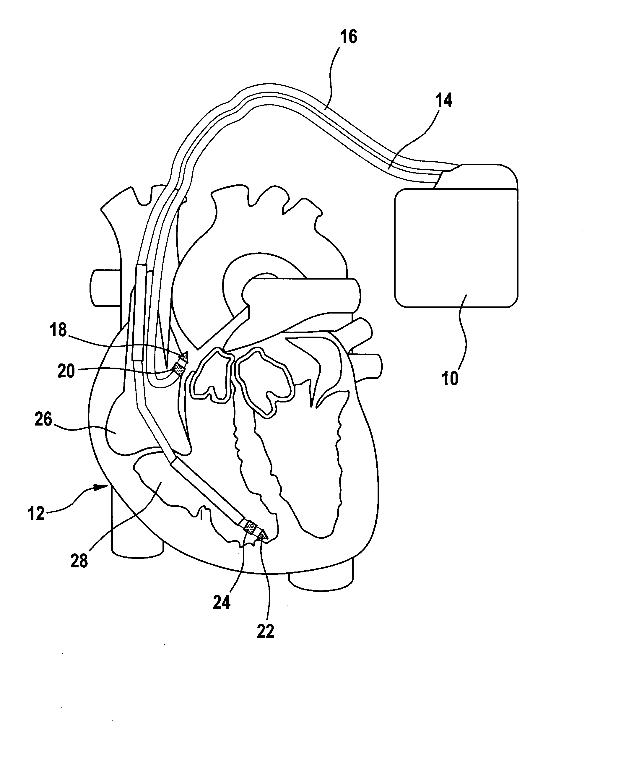
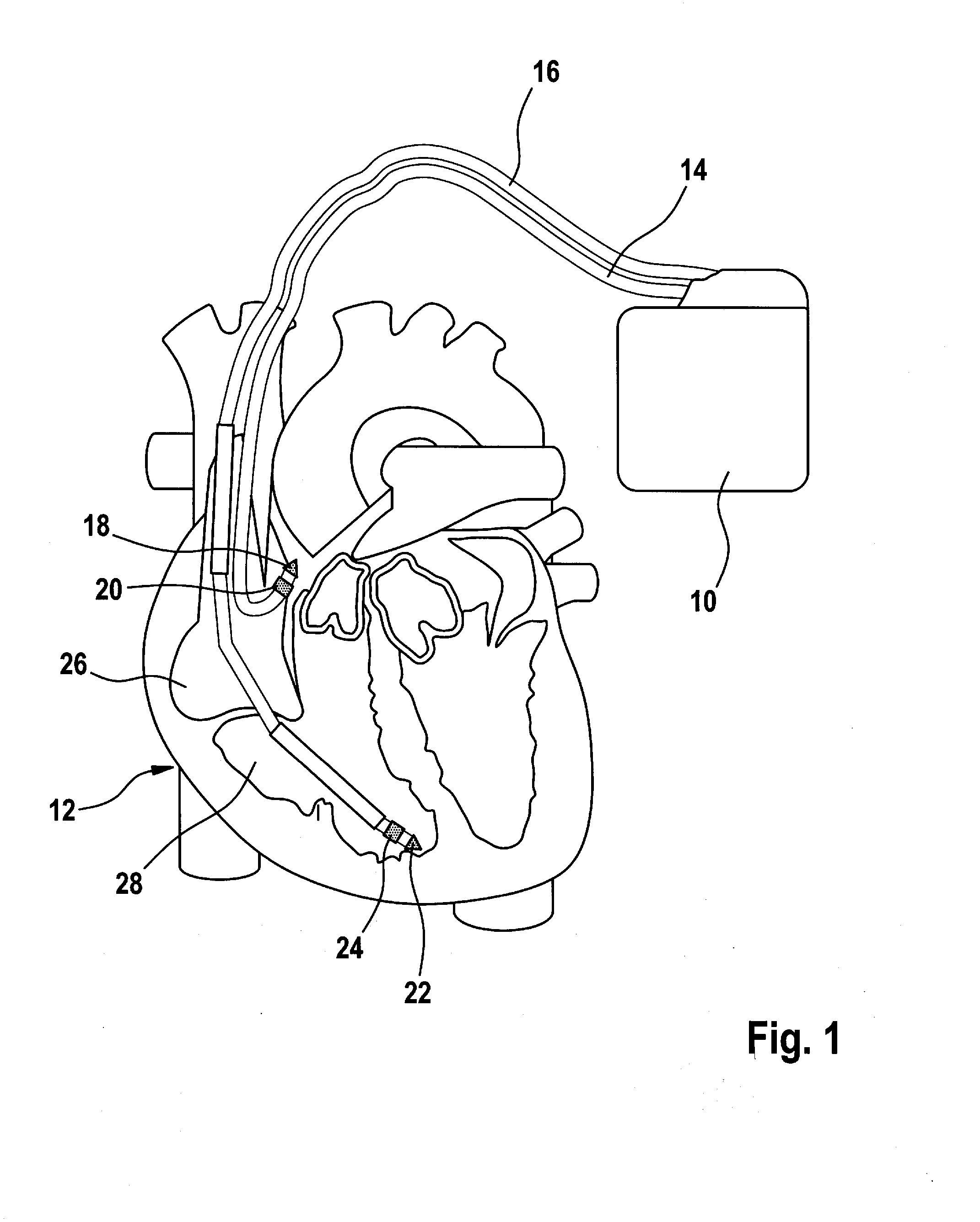
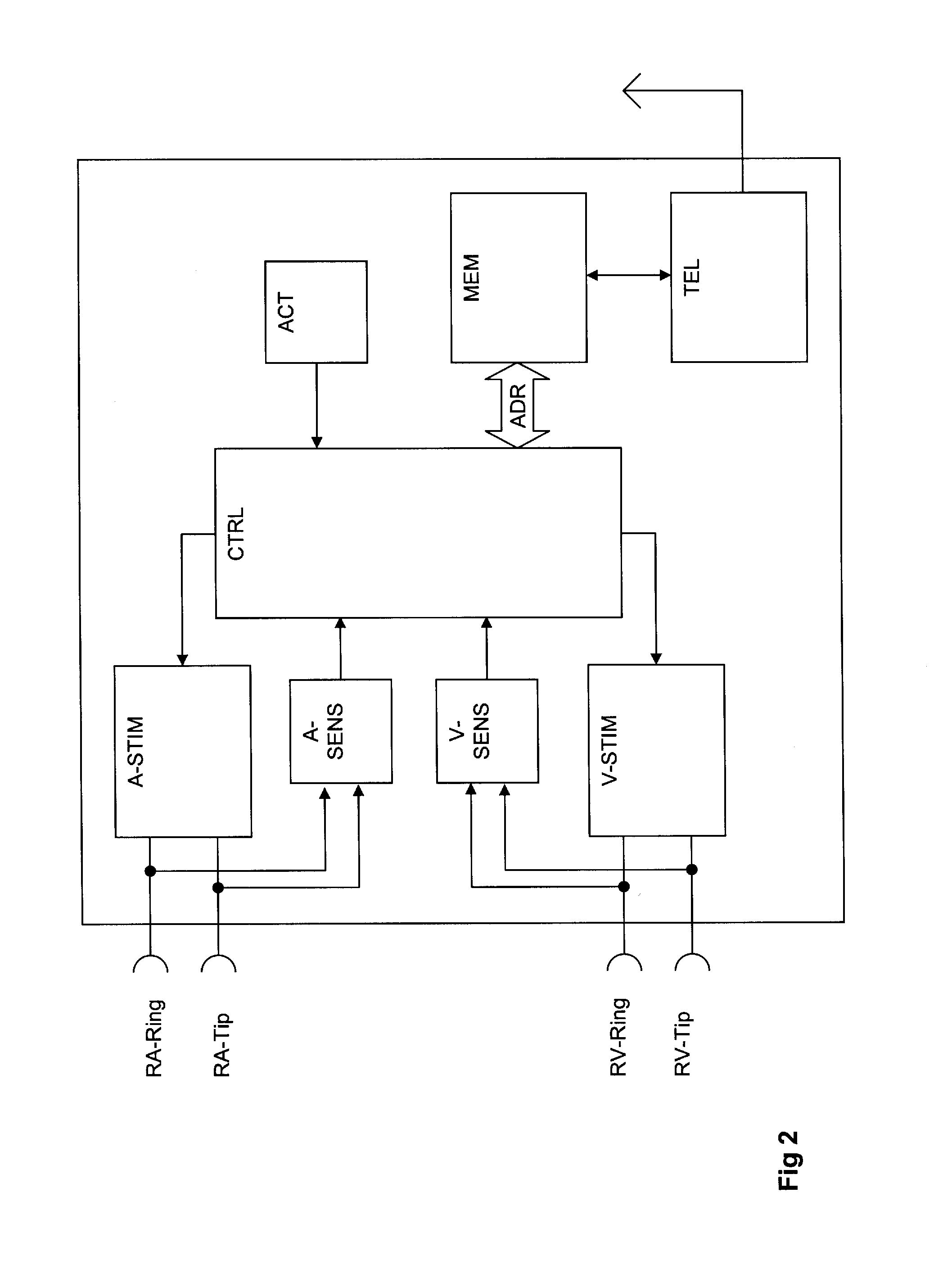
[0068] In FIGS. 1 and 2 an electrostimulator according to the invention is illustrated by way of an exemplary dual chamber pacemaker 10 (pacer 10).

[0069] Referring to FIG. 1 a dual chamber pacemaker 10 connected to pacing / sensing leads placed in a heart 12 is illustrated. The pacemaker 10 is coupled to a heart 12 by way of leads 14 and 16, the lead 14 having a pair of right atrial electrodes 18 and 20 that are in contact with the right atria 26 of the heart 12, and the lead 16 having a pair of electrodes 22 and 24 that are in contact with the right ventricle 28 of heart 12. The electrodes 18 and 22 are tip-electrodes at the very dital end of leads 14 and 15, respectively. Electrode 18 is a right atrial tip electrode RA-Tip and electrode 22 is a right ventricular tip electrode 22. Electrodes 20 and 24 are designed as ring electrode in close proximity but electrically isolated from the respective tip electrodes 18 and 22. Electrode 20 forms a righ...


PUM


Abstract

An implantable cardiac electrostimulator comprising an atrial sensing channel for processing intracardiac electrogram signals and for detecting signals corresponding to atrial activity and for generating an atrial sense event signal upon detection of a signal corresponding to atrial activity, a ventricular sensing channel for processing intracardiac electrogram signals and for detecting signals corresponding to ventricular activity and for generating a ventricular sense event signal upon detection of a signal corresponding to ventricular activity, a VES detector being operatively connected to said atrial and ventricular sensing channel and being adapted to detect ventricular extrasystoles an atrial stimulation pulse generator a ventricular stimulation pulse generator a stimulation control unit being operatively connected to said atrial stimulation pulse generator and said ventricular stimulation pulse generator. The stimulation control unit is adapted to determine a scheduled time of delivery of an atrial stimulation pulse (T(A)) and a scheduled time of delivery of ventricular stimulation pulse (T(V)). The stimulation control unit is further adapted to trigger said atrial stimulation pulse generator or said ventricular stimulation pulse generator at the scheduled point of time T(A) or T(V), respectively, if no atrial sense event signal is generated before time out of an atrial escape interval (VAI), said atrial escape interval timing out at T(A), or if no ventricular sense event signal is generated before time out of a ventricular escape interval (VEI), said ventricular escape interval timing out at T(V), respectively. T(A) und T(V) are determined depending upon detection of a ventricular extra systole while maintaining a proper atrioventricular synchrony by setting a physiologically adequate A-V-delay between T(A) and corresponding T(V).

Description

FIELD OF INVENTION [0001] The present invention relates to implantable electrostimulators, including pacemakers, defibrillators and cardioverters, which stimulate cardiac tissue electrically to control the patient's heart rhythm. In particular the present application is directed to an implantable electrostimulator comprising rate smoothing means for smoothing a heart rate or a stimulation rate, respectively, after after a ventricular extra systole. BACKGROUND OF THE INVENTION [0002] A ventricular extra systole is an ectopic spontaneous ventricular contraction arising in the ventricles and stimulating the myocardium prematurely. [0003] A ventricular extrasystole (VES) with a short coupling interval is frequently followed by a relatively long compensatory pause before returning to presystolic intrinsic ventricular cycle length. Such a so-called short-long sequence has adverse effects on cardiac hemodynamics due to irregular ventricular filling. Moreover, the pause-dependent ventricula...

Claims


Application Information

Patent Timeline
IPC IPC(8): A61N1/362
CPCA61N1/3682A61N1/3622
Inventor LANG, VOLKERLIAN, JIEMUSSIG, DIRK
Owner BIOTRONIK SE & CO KG
Learn More