

Multi-spark ignition system
a multi-spark ignition and ignition system technology, applied in the direction of electric ignition installation, mechanical equipment, machines/engines, etc., can solve the problems of complicated and bulky interface of multi-spark ignition system, and achieve the effect of simple and compact connection interfa
- Summary
- Abstract
- Description
- Claims
- Application Information
AI Technical Summary
Benefits of technology
Problems solved by technology
Method used
Image

Examples
first embodiment
[0036]A multi-spark ignition system according to the invention will be described with reference to FIGS. 1-5.
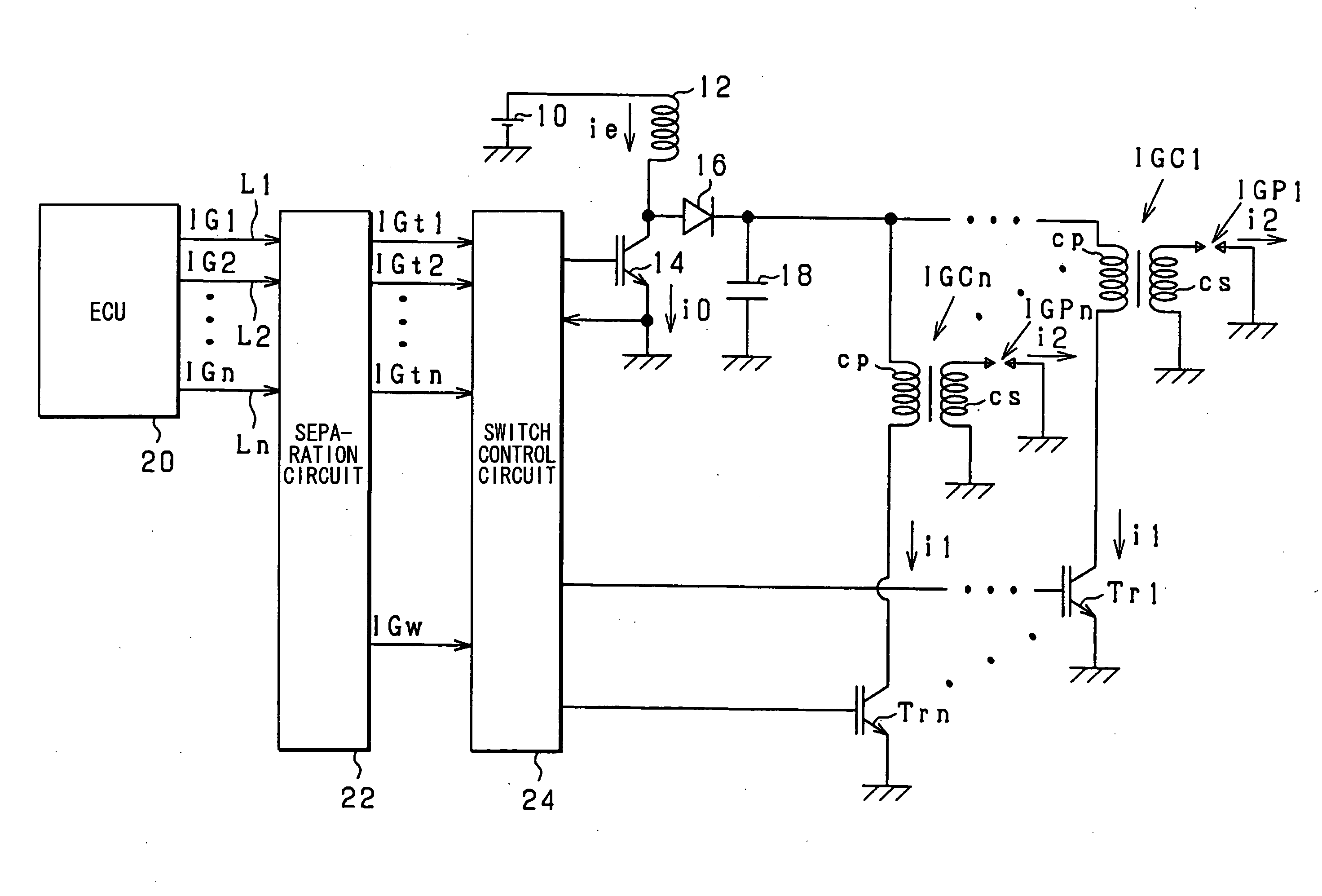
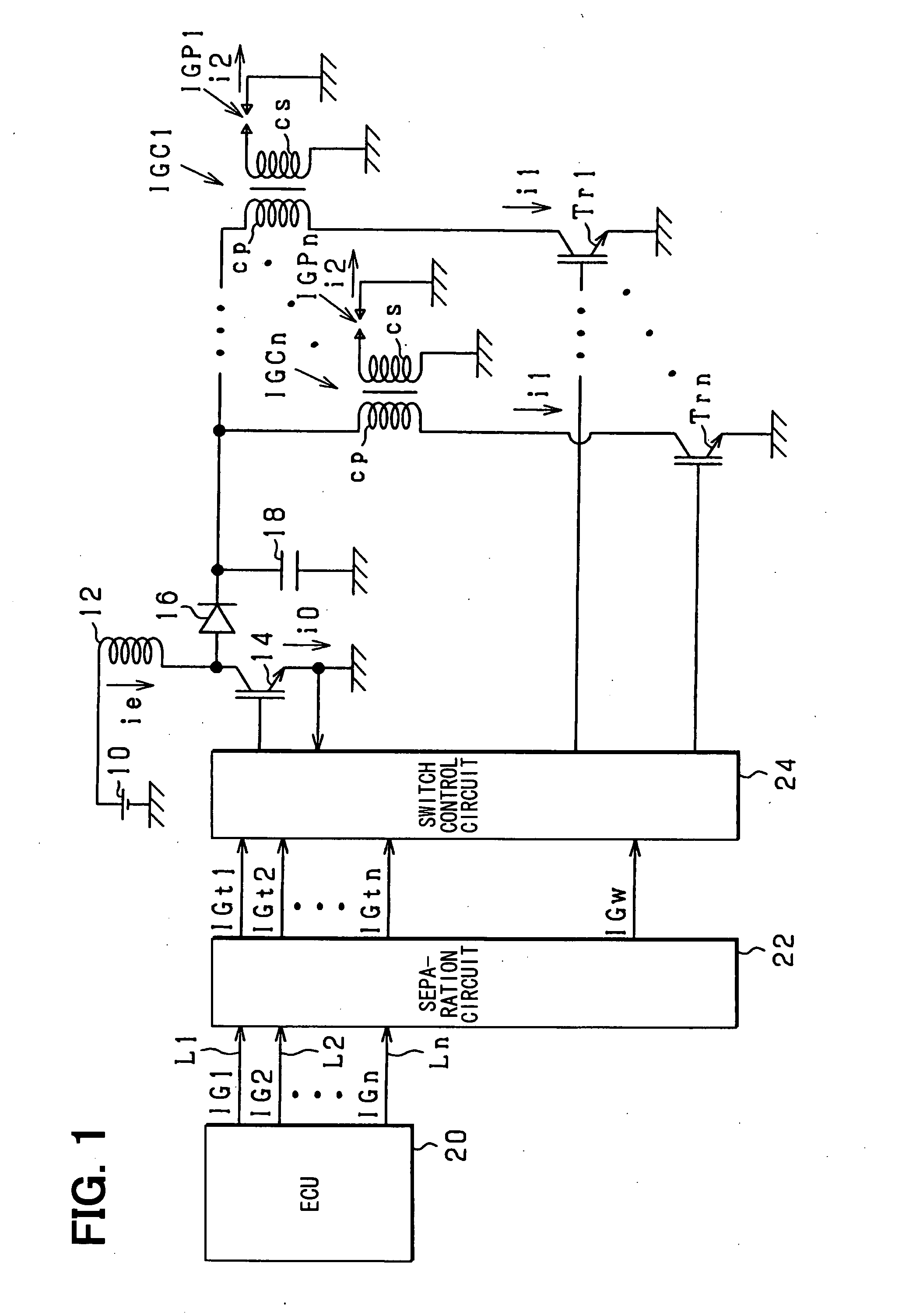
[0037]The multi-spark ignition system includes a battery 10, a energy storing coil 12, a switching element 14, a diode 16, a capacitor 18, an engine control unit (hereinafter referred to as ECU) 20, a separation circuit 22, a switch control circuit 24, a plurality of ignition coils IGC1-IGCn, a plurality of switching elements Tr1-Tm, etc.
[0038]The energy storing coil 12 has one end connected with the battery 10 and the other end connected to a ground via the switching element 14 and to one end of the capacitor 18 via the diode 16. The diode 16 is connected so as to allow current flowing to the capacitor 18 and to prevent current from flowing back. Each of the ignition coils IGC1-IGCn has a primary coil cp and a secondary coil Cs. The other end of the energy storing coil 12 is also connected with one end of each primary coil cp. The other end of the capacitor 18 is connected w...
third embodiment
[0062]A multi-spark ignition system according to the invention will be described with reference to FIGS. 1 and 11-14.
[0063]As shown in FIG. 11, the i-th consolidated signal IGi includes a single pulse P0 and seven short pulses Pn. The single pulse P0 includes an energy storing command signal component for the ignition by the i-th spark plug. The seven short pulses Pn include the energy discharging period command signal component for the ignition by the i-th spark plug. The i-th energy storing command signal IGti is formed a preset time after the rising edge of the single pulse P0, and the energy discharging period command signal IGw is formed just when the energy storing command signal falls down. The energy discharging period command signal IGw falls down a preset time after the last short pulse Pn falls down.
[0064]As shown in FIG. 12, the separation circuit 22 of the third embodiment includes wave-form shaping circuits 301-30n, a t-signal generation circuits 681-68n, a RS flip-flo...
fourth embodiment
[0073]A multi-spark ignition system according to the invention will be described with reference to FIGS. 1 and 15-16.
[0074]As shown in FIG. 15, the separation circuit 22 of the fourth embodiment includes wave-form shaping circuits 301-30n, higher side comparators 1201-120n, lower side comparators 1221-122n, inverters 1241-124n, AND circuits 1261-126n, an OR circuit 128, etc.
[0075]As shown in FIG. 16, the consolidated signal has three levels—a maximum level, a medium level and a minimum level. For example, the level of the i-th consolidated signal IGi becomes medium after it becomes maximum. The maximum level of the consolidated signal includes a signal to store electric energy into the energy storing coil 12. The timing of shifting from the medium level to the minimum level of the consolidated signal includes a signal to terminate the energy discharging by the i-th spark plug IGPi. The consolidated signal (e.g. IG1), the wave form of which has been shaped, is inputted to the respect...
PUM
 Abstract
Description
Claims
Application Information