
Spinal reamer

a technology of spinal reamer and reamer, which is applied in the field of spinal reamer, can solve the problems of male retrograde ejaculation, risky spine, and combined risks of general anesthesia and vascular injury

Active Publication Date: 2007-11-22
IMPLANT LTD
View PDF14 Cites 67 Cited by
  • Summary
  • Abstract
  • Description
  • Claims
  • Application Information

AI Technical Summary

Benefits of technology

[0007]The present invention seeks to provide spinal reamers for use in surgical procedures, such as installing spinal prostheses, as is described more in detail hereinbelow. For example, following transforaminal posterior lumbar discectomy, a portion of the disc and endplate may remain behind. The spinal reamer apparatus may be used to ream, cut and / or remove material or debris.

Problems solved by technology

This relatively large cross-section usually necessitates a mostly anterior retroperitoneal (from the front of the abdomen but staying outside the intestinal sac) approach to the spine which may be risky.
The risks of general anesthesia are coupled with risks of vascular injury and retrograde ejaculation in males.

Method used


Image

  • Spinal reamer
  • Spinal reamer
  • Spinal reamer

Examples


Embodiment Construction

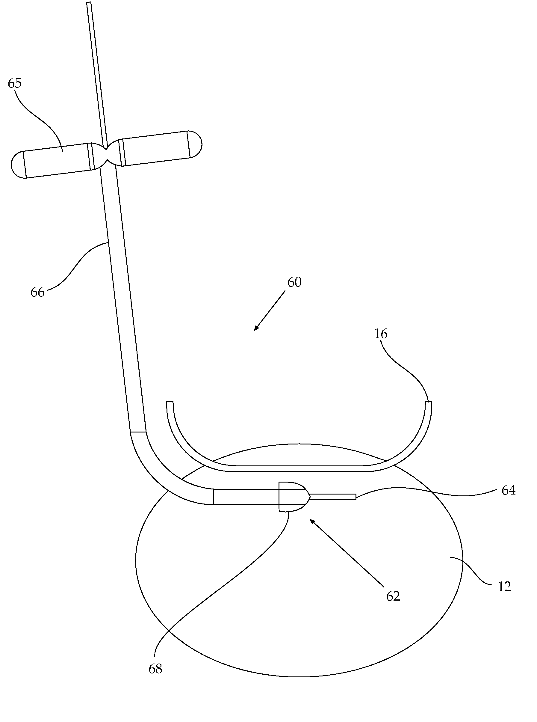
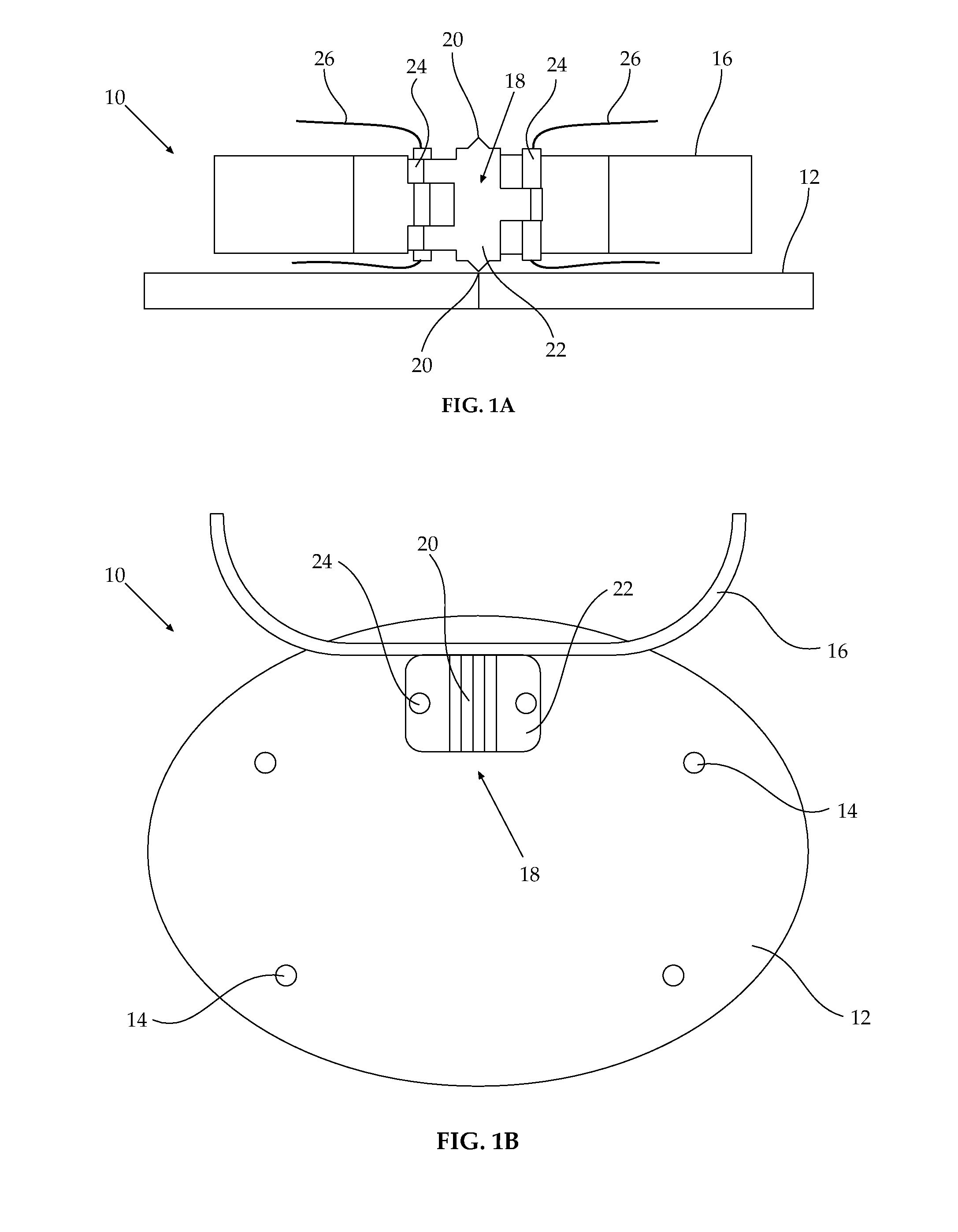
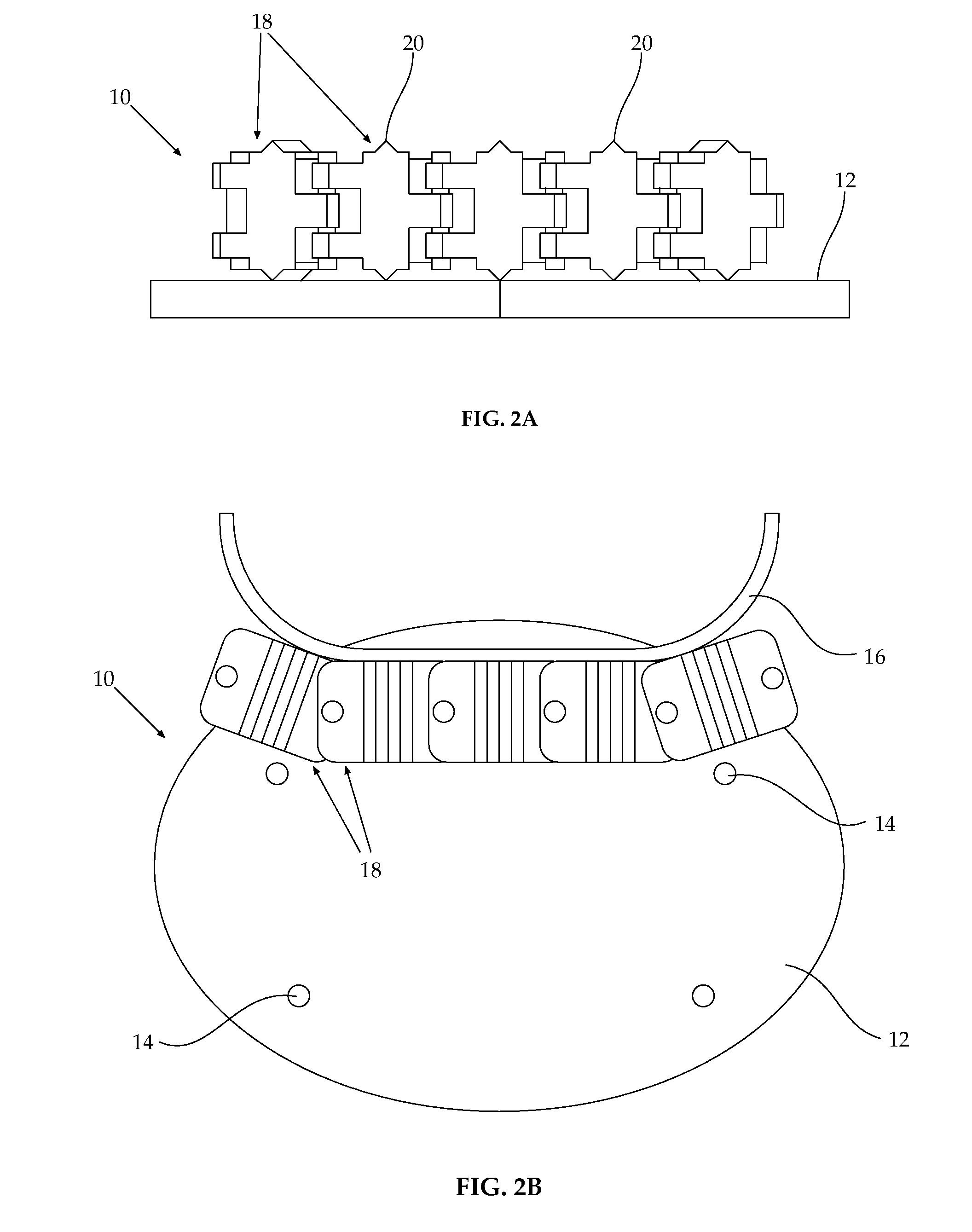
[0017]Reference is now made to FIGS. 1A and 1B, which illustrate spinal reamer apparatus 10, constructed and operative in accordance with a non-limiting embodiment of the present invention.

[0018]Spinal reamer apparatus 10 includes a reference base 12 with mounting provisions 14 for mounting in a region of posterior lumbar spinal structure. For example, mounting provisions 14 may be mounting holes positioned to correspond with the exact position of mounting hardware (e.g., pedicle screws) or mounting holes of a spinal prosthesis (not shown) to be installed in the spine, e.g., posterior spinal structure or intravertebral or intervertebral space. For example, mounting provisions 14 may be mounting holes positioned to correspond with the exact position of holes drilled into bone for mounting pedicle screws of the implant described in U.S. Pat. No. 7,011,685, the disclosure of which is incorporated herein by reference.

[0019]A track 16 may be fixed to reference base 12. Track 16 in the no...


PUM


Abstract

Spinal reamer apparatus including a reference base with mounting provisions for mounting in a region of posterior lumbar spinal structure, a non-straight track fixed to the reference base, and at least one reaming cutter element arranged to move along the track.

Description

CROSS-REFERENCE TO RELATED APPLICATIONS[0001]This application claims priority under 35 USC §119 to U.S. Provisional Patent Application Ser. No. 60 / 789,219, filed on Apr. 5, 2006, which is incorporated herein by reference.FIELD OF THE INVENTION[0002]The present invention relates to spinal reamers for use in surgical procedures, such as installing spinal prostheses.BACKGROUND OF THE INVENTION[0003]Spinal disc or partial spinal disc replacement is a common procedure in Europe with thousands having been performed already and is now commencing in the United States. Examples of such replacement discs are ProDisc (Spine Solutions, Inc.) and SB Charite III (Link Spine Group, Inc.)[0004]By replacing a disc and not merely fusing vertebrae, which is the common alternative practice to disc replacement, the mobility of the patient's adjacent discs may be preserved and thus may delay the onset of arthritic changes to adjacent vertebrae.[0005]A typical disc replacement unit is approximately 30 mil...

Claims


Application Information

Patent Timeline
Patent Type & Authority Applications(United States)
IPC IPC(8): A61B17/56A61B17/16A61B17/00
CPCA61B17/1637A61B2017/145A61B2017/143A61B17/1671A61B17/149
Inventor ARNIN, URIFLEISCHER, SHAI
Owner IMPLANT LTD
Features
  • Generate Ideas
  • Intellectual Property
  • Life Sciences
  • Materials
  • Tech Scout
  • Unparalleled Data Quality
  • Higher Quality Content
  • 60% Fewer Hallucinations
Learn More