Spinal disc prosthesis and methods of use

a technology for spinal discs and prostheses, applied in the field of spinal disc prostheses and methods of use, can solve the problems of design of prosthetic discs, drastic treatments are usually insufficient to restore normal disc function, and further problems, and achieve the effect of facilitating sagittal, lateral, and polar vertebral movemen

Active Publication Date: 2006-10-26
DOTY KEITH L
View PDF70 Cites 83 Cited by
  • Summary
  • Abstract
  • Description
  • Claims
  • Application Information

AI Technical Summary

Benefits of technology

[0013] The subject invention provides a spinal disc prosthesis capable of providing spatial movement with up to 6 degrees of freedom. In a preferred embodiment, the device of the subject invention facilitates sagital, lateral, and polar vertebral movement when utilized in the spine of an animal. In one embodiment, the modular spinal disc prosthesis of the subject invention comprises superior and inferior vertebral plates, as well as a flexible, boot-protected replaceable 6-DOF modular prosthetic disc mechanism (linkage). The up to 6 degrees of freedom provided by the subject in

Problems solved by technology

The later treatment, while providing short term relief, often leads to excessive forces on facet joints adjacent to the fusion and creates further problems over time.
Drastic treatments are usually unable to restore normal disc function.
Natural spinal motions place severe requirements on the design of a prosthetic disc; simple rotational joints are not able meet those requirements.
In addition, motion coupling between axial and lateral bending and other functional spinal units involved in the overall spinal motion increases the complexity and difficulty in developing a prosthetic disc replacement that realizes natural spinal motion.
However, these designs limit motion to rotation only about the socket when the two plates are in contact.
Further, when the two plates, as described in the cited patents, are not in contact, the devices are unable to provide stability to the intervertebral interface, which can allow free motion and lead to disc related spondylolisthesis, FSU instability and excessive facet loading.
In addition, the sliding disc core devices of the Bryan et al. and SB Charité™ devices do not

Method used


Image

  • Spinal disc prosthesis and methods of use
  • Spinal disc prosthesis and methods of use
  • Spinal disc prosthesis and methods of use

Examples


example 1

Ball-and-Socket Joint

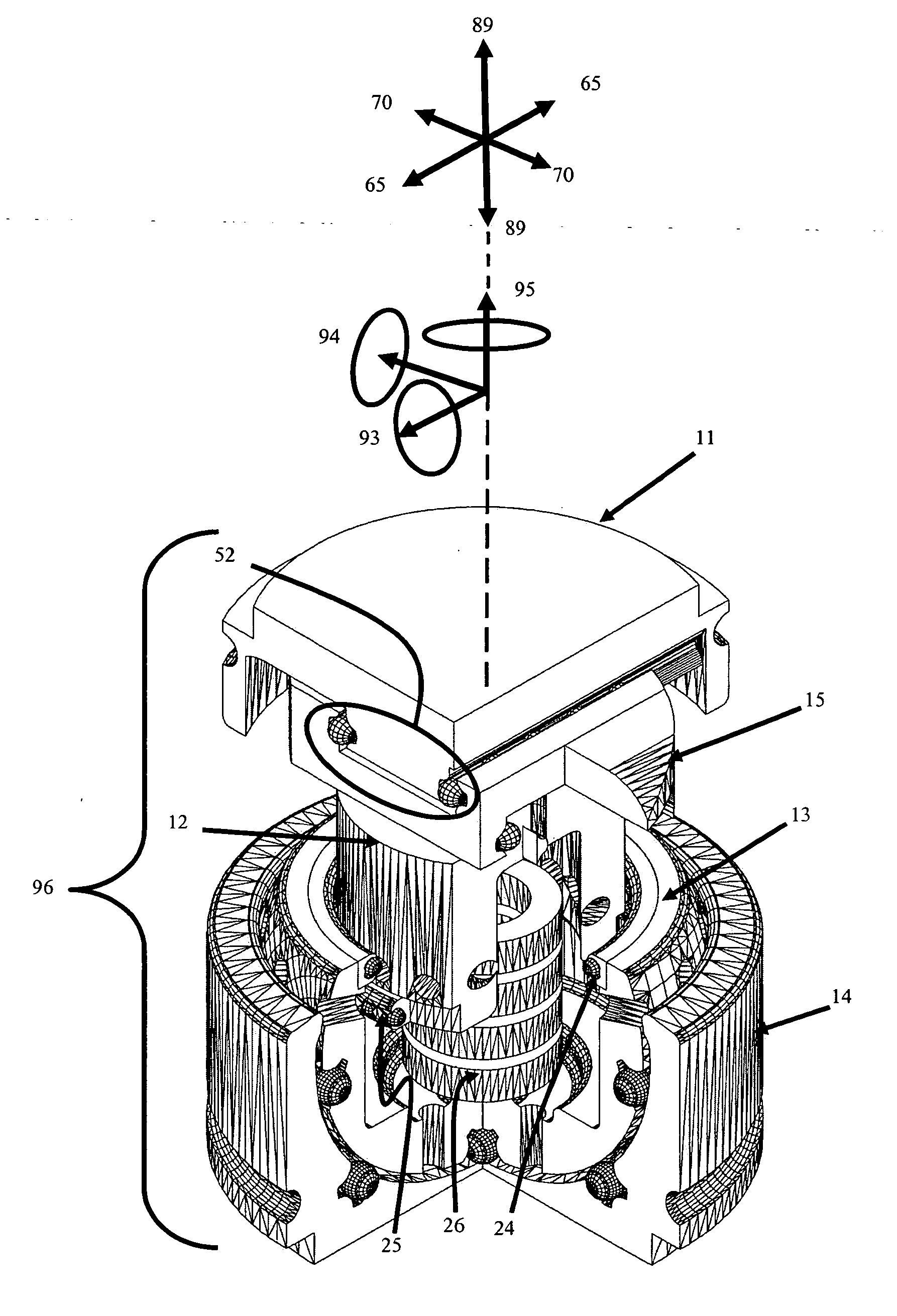
[0113] In one embodiment, the chambered-ball 13 (FIG. 9) fits into the spherical cavity 118 of the socket-base 14 (FIG. 8) to form a ball-and-socket joint 37 (FIG. 10). In a preferred embodiment, the ball is free to rotate about three orthogonal axes 93, 94, and 95 (FIG. 14) within the socket cavity. Thus, in one embodiment, the ball-and-socket joint allows the spatial mechanism to arbitrarily orient or point in three-dimensional space, within the angle limits of the linkage, the more distal elements of the device: the piston 12, plane-bearing guide 15, cap-plate 11, and superior vertebral plate 2. In the lower pair embodiment, FIG. 28, the elements 214, and 213 form a spherical kinematic pair, i.e., the ball-and-socket joint.

[0114] In an alternative embodiment, a girdle ring-bearing 18 and a socket ring-bearing 19, illustrated in FIG. 5, can be utilized with the ball-and-socket joint. FIG. 5 does not illustrate bearing separators and retention matrices that m...

example 2

Polar-Axis Prismatic Joint

[0120] The polar-axis prismatic joint can comprise the combination of the spherical chambered-ball 13 (FIG. 9) and the cylindrical piston 12 (FIG. 11) to form a prismatic pair. In one embodiment, the prismatic pair also comprises bearings 24 and 25. In a further embodiment, the cross-section of the chambered-ball cavity 35 is similar or identical to the piston cross-section, but should possess slightly greater radius of curvature to accommodate the piston and allow for bearing clearances. In the lower pair embodiment as illustrated in FIG. 28, the elements 213, and 212 form a cylindrical pair to provide a polar-axis prismatic joint.

[0121] Hydraulic portals 20 circle the mouth of the chambered-ball 13 to allow lubricating fluid to flow out of the chambered-ball cavity 35 to other moving parts. Four hydraulic portals 20 may pierce the bottom, circling a polar bearing 30 (FIG. 10, FIG. 12) that can be positioned in the base of the chambered ball

[0122] The p...

example 3

Spherical-Polar-Axis Linkage

[0130] In one embodiment, linking the piston 12, with a spring 26, chambered-ball 13, and socket-base 14 provides a 4-DOF spherical-polar-prismatic manipulator with load bearing capacity (FIG. 14). As the more distal elements of the prosthesis, i.e., the plane-bearing guide 15, cap-plate 11, and superior vertebral plate 2, move, the spherical manipulator (ball-and-socket joint) track their orientation 93, 94, 95 and distance traveled 89 along the polar axis 113 (FIG. 10) from the chambered-ball center.

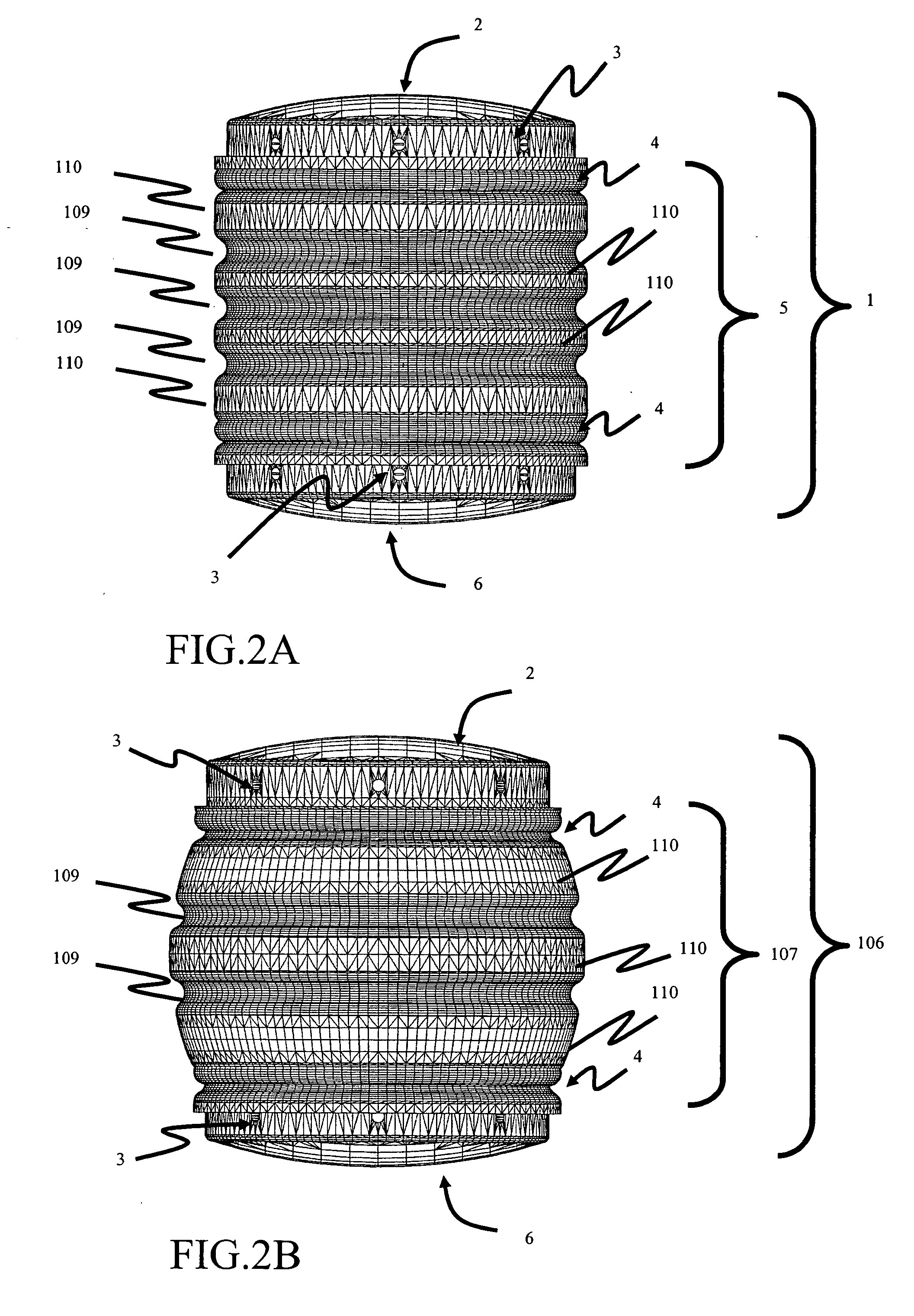
[0131]FIGS. 15A, 15B and 15C show the operation of the spherical-polar-axis linkage 115 in flexion 90, neutral 91 and extension 92. As spinal muscles move the superior vertebra of the FSU, loading on the spring or spring-like mechanism or material within the piston changes. In a further embodiment, the principal spring axis coincides and, thus, rotates with, the polar-axis 113, causing the forces acting on the spring to either rotate the spring by means of...


PUM

PropertyMeasurementUnit
Lengthaaaaaaaaaa
Angleaaaaaaaaaa
Lengthaaaaaaaaaa

Abstract

The subject invention provides a modular six-degrees-of-freedom spatial mechanism for spinal disc prosthesis, with three rotational and three translational degrees-of-freedom within the entire workspace of a Functional Spinal Unit (FSU). The prosthetic disc mechanism attaches to upper and lower plates anchored between vertebrae of an FSU. Scaling, conjoined with motion limit stops, allows the device to realize almost any nominal spinal articulation, from the cervical to lumbar regions.

Description

BACKGROUND OF INVENTION [0001] Spinal disc herniation, a common ailment, often induces pain, as well as neurologically and physiologically debilitating processes for which relief becomes paramount. If conservative treatments fail, the more drastic measures of discectomies and spinal fusion may be indicated. The later treatment, while providing short term relief, often leads to excessive forces on facet joints adjacent to the fusion and creates further problems over time. Drastic treatments are usually unable to restore normal disc function. The loss of disc function has led to a number of disc prosthesis that attempt to provide natural motion. [0002] The literature documents that the instantaneous axis of rotation (IAR) during sagittal rotation of the superior vertebra with respect to the inferior vertebra of a Functional Spinal Unit (FSU) in the cervical spine moves significant distances during flexion and extension of the spine (Mameren H. van, Sanches H., Beursgens J., Drukker, J...

Claims


Application Information

Patent Timeline
IPC IPC(8): A61F2/44
CPCA61F2/30742A61F2310/00748A61F2/441A61F2/4425A61F2002/30331A61F2002/30492A61F2002/30495A61F2002/30507A61F2002/30563A61F2002/30566A61F2002/30581A61F2002/30601A61F2002/3064A61F2002/30644A61F2002/30649A61F2002/30662A61F2002/30673A61F2002/30685A61F2002/30841A61F2002/443A61F2002/4495A61F2220/0025A61F2220/0033A61F2310/00017A61F2310/00023A61F2310/00029A61F2/30744A61F2002/30639
Inventor DOTY, KEITH L.
Owner DOTY KEITH L
Why Eureka
Try Eureka