Distractor for lumbar insertion instrument

a technology of lumbar insertion and instrument, which is applied in the field of instruments for inserting intervertebral implants, can solve the problems of unacceptably high complication rate of som

Active Publication Date: 2009-06-16
CENTINEL SPINE LLC
View PDF24 Cites 83 Cited by
  • Summary
  • Abstract
  • Description
  • Claims
  • Application Information

AI Technical Summary

Benefits of technology

[0009]A purpose of the present invention is to provide a new and improved instrument and method for inserting an intervertebral disc implant.
[0017]Thus, it is an object of the present invention to provide a new and improved instrument for distracting upper and lower parts of an intervertebral disc implant.
[0018]It is another object of the present invention to provide a new and improved method for separating the upper and lower parts of an intervertebral disc implant.

Problems solved by technology

However, reported clinical results vary considerably, and complication rates are considered by some to be unacceptably high.
However, both of these instruments are suitable only for inserting complete implants.

Method used


Image

  • Distractor for lumbar insertion instrument
  • Distractor for lumbar insertion instrument
  • Distractor for lumbar insertion instrument

Examples


Embodiment Construction

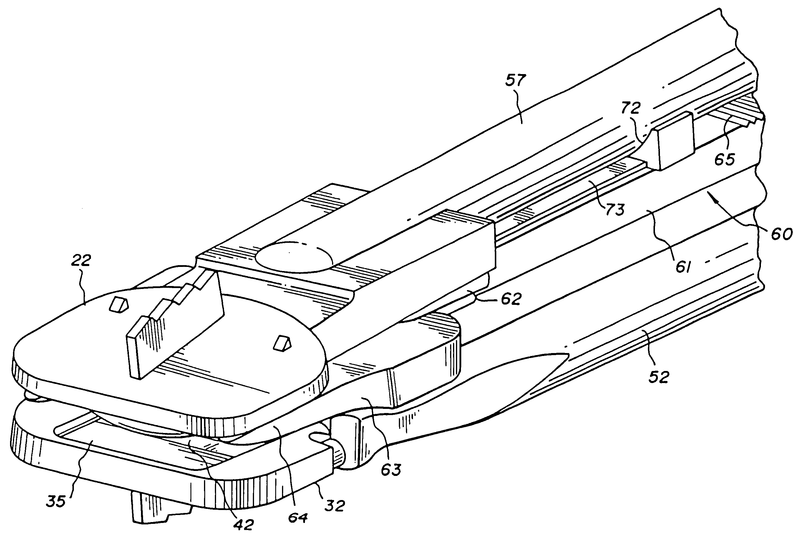
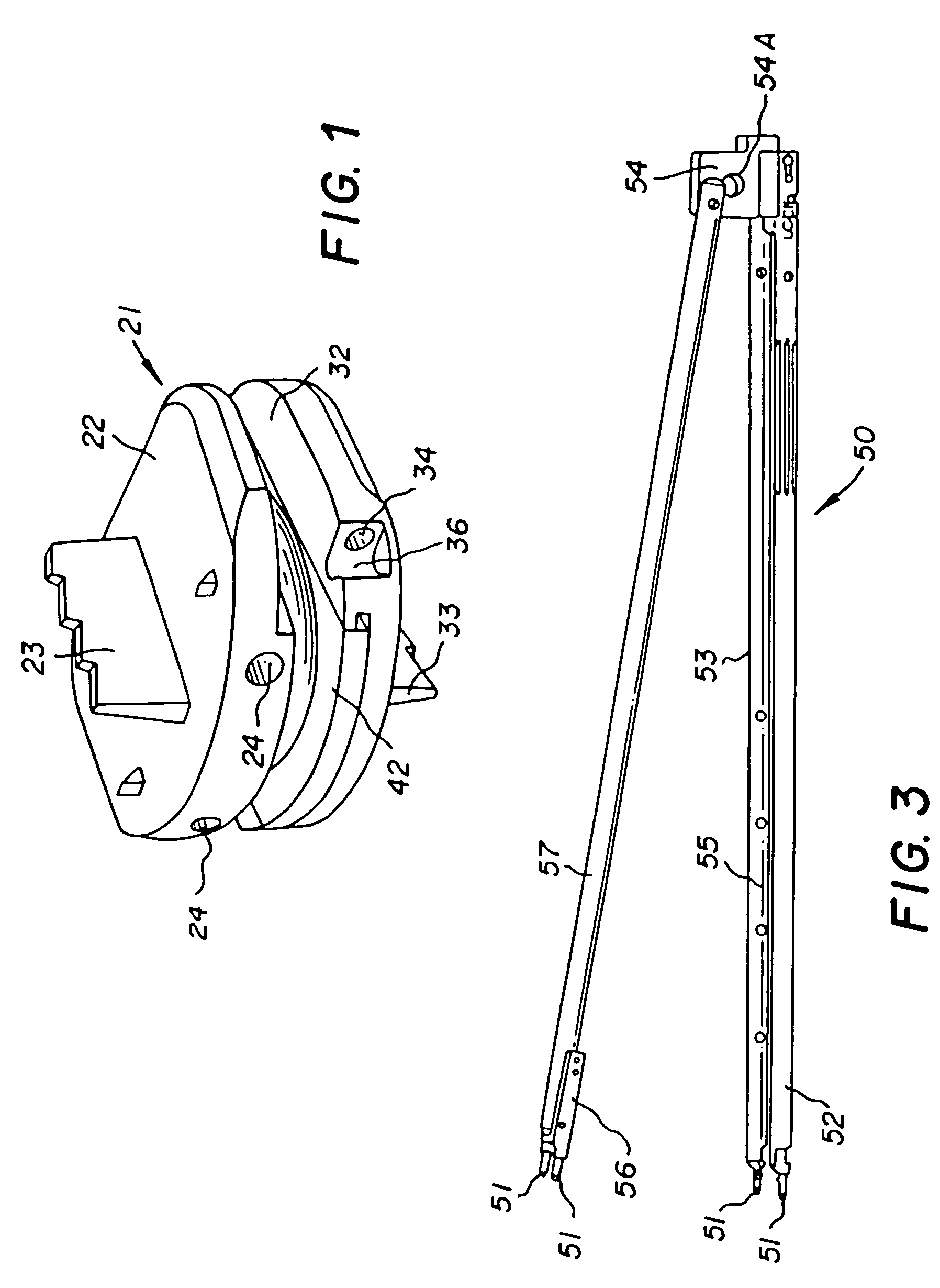
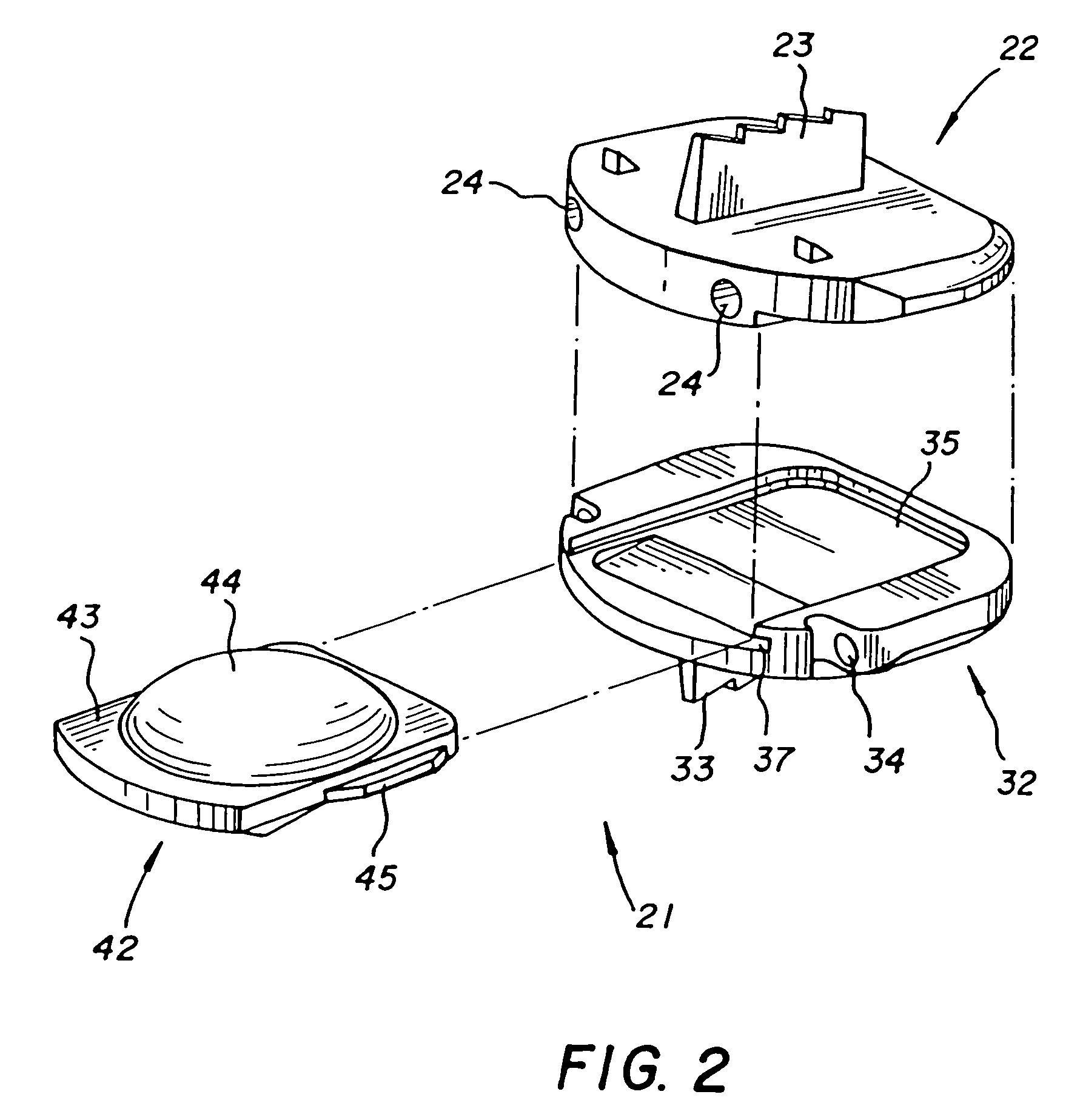
[0035]Referring now to the drawings, like elements are represented by like numerals throughout the several views. As stated above, embodiments of the present invention are directed to instruments and methods for inserting artificial intervertebral disc implants 21 or the like. As known in the art, prior to inserting of an intervertebral disc implant 21, the intervertebral space must be cleaned out with instruments such as elevators and / or chisels. After the intervertebral space has been cleaned out in preparation for receiving intervertebral disc implant 21, the next step is to determine the precise size of an inlay protrusion 44 of a pivot element 42 (which is located between an upper part 22 and a lower part 32 of implant 21) which provides a correct overall height for disc implant 21 for that particular (height) intervertebral space. This determination is accomplished by providing a set of trial implants of different sizes. The operator thus selects by experience the trial implan...


PUM


Abstract

An instrument and method are disclosed for inserting an artificial intervertebral disc implant having upper and lower parts and a pivot element therebetween into an intervertebral space. The instrument has a mounting structure, and an elongated upper arm and elongated lower arms, the arms being pivotally attached to the mounting structure. A distractor separates the upper and lower arms, and hence the upper and lower parts, when moving along the arms so as to permit insertion of the pivot element. The distractor includes a fork arm that extends beyond a main body thereof to engage and support with heads thereof a facing surface of the upper and / or lower part during and following separation of the parts.

Description

FIELD OF THE INVENTION[0001]This invention relates to instruments for inserting intervertebral implants, and more specifically to new and improved instruments and methods for inserting an artificial intervertebral disc implant into an intervertebral space.BACKGROUND OF THE INVENTION[0002]Currently, when it is necessary to completely remove a disc from between adjacent vertebrae, the conventional procedure is to fuse the adjacent vertebrae together. This “spinal fusion” procedure is a widely accepted surgical treatment for symptomatic lumbar degenerative disc disease. However, reported clinical results vary considerably, and complication rates are considered by some to be unacceptably high.[0003]More recently, there have been important developments in the field of disc replacement, namely disc arthoplasty, which involves the insertion of an artificial intervertebral disc implant into the intervertebral space between adjacent vertebrae, and which allows limited universal movement of t...

Claims


Application Information

Patent Timeline
Patent Type & Authority Patents(United States)
IPC IPC(8): A61B17/58
CPCA61F2/4611A61B2017/0256A61F2002/30383A61F2002/30884A61F2002/443A61F2002/4627A61F2002/4628A61F2220/0025A61F2/34A61B17/56A61B17/88A61B17/72
Inventor BERTAGNOLI, RUDIMARNAY, THEIRRYECKHOF, STEPHANGEISERT, CHRISTOPHEKUFELD, EDUARD
Owner CENTINEL SPINE LLC
Why Eureka
Try Eureka