Selective axis anchor screw posterior lumbar plating system

Inactive Publication Date: 2005-09-29
MEDICAL DEVICE ADVISORY DEV GROUP
View PDF99 Cites 67 Cited by
  • Summary
  • Abstract
  • Description
  • Claims
  • Application Information

AI Technical Summary

Benefits of technology

[0023] One advantage provided by the spinal fixation systems described herein is the provision of a selective axis feature whereby the clamp assembly engages the connecting beam at a substantially perpendicular angle. In particular, on assembly, the spherical shoulder of the anchor screw loads against the spherical seat of the lower clamp. The swing bolt of the anchor screw assembly passes up through the central passage formed by the clamp assembly. The fastene

Problems solved by technology

However, because the system of the '166 patent is polyaxial, i.e., may pivot about multiple axes, there is greater risk of the system coming out of alignment when the patient resumes normal physical activity.
This system is also very comp

Method used


Image

  • Selective axis anchor screw posterior lumbar plating system
  • Selective axis anchor screw posterior lumbar plating system
  • Selective axis anchor screw posterior lumbar plating system

Examples


Embodiment Construction

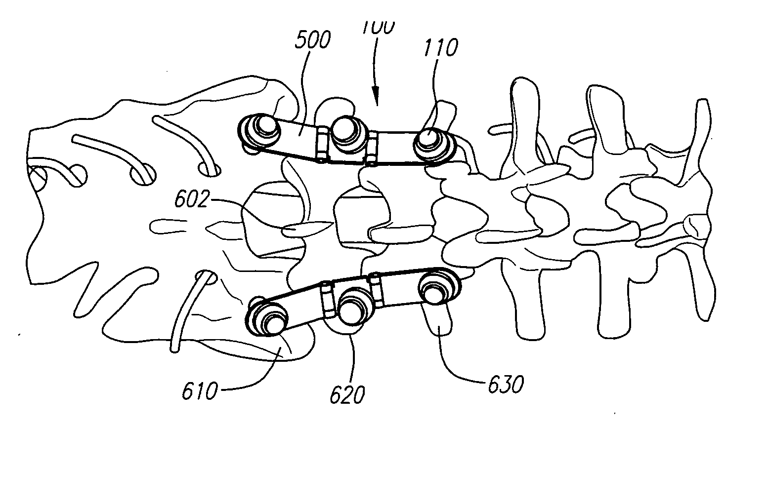
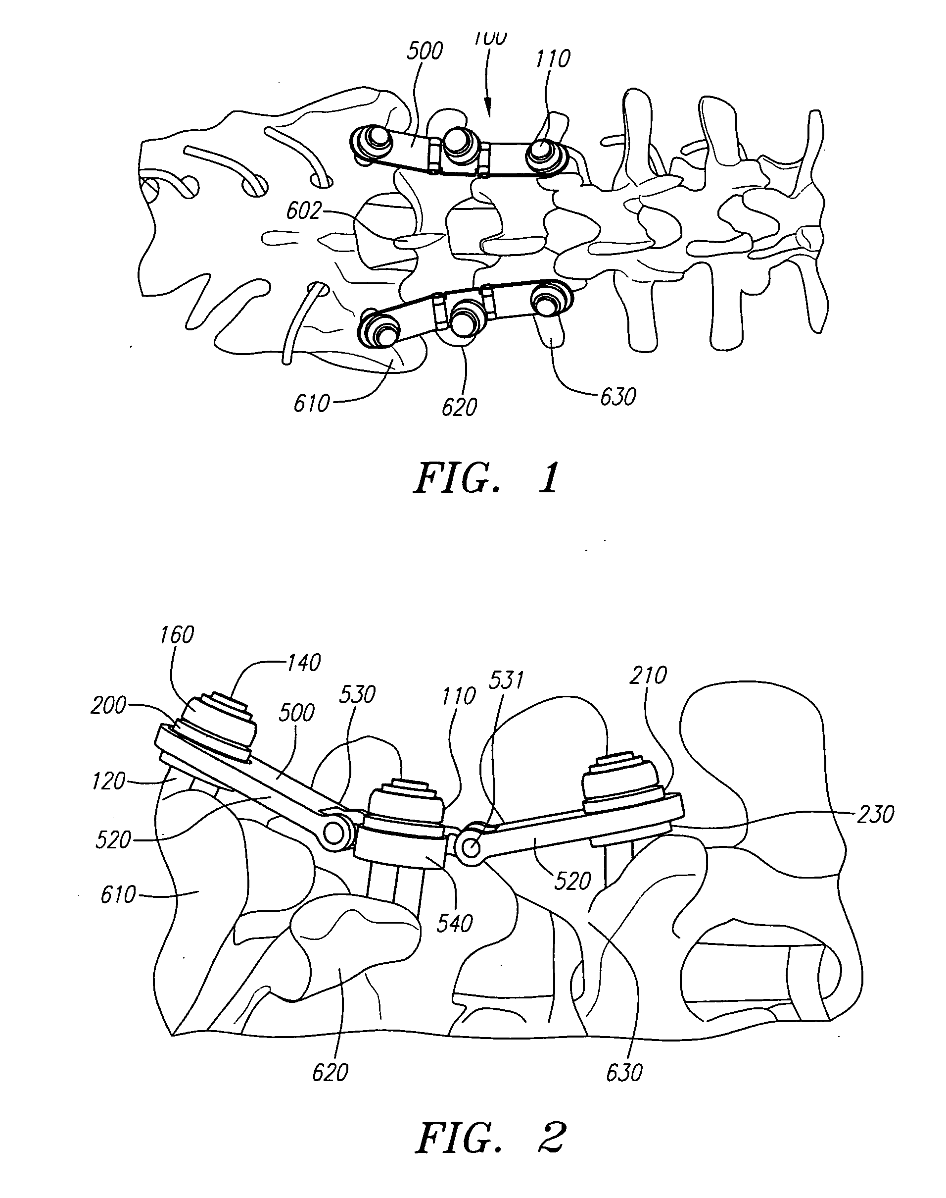
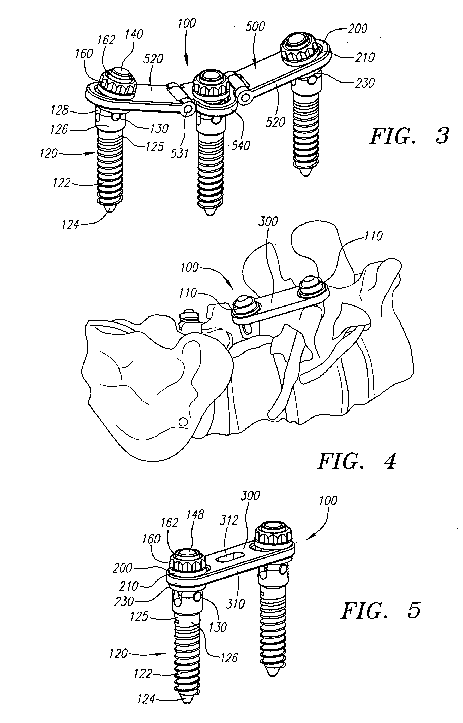
[0065] Turning now to the drawings, FIGS. 1-6 show preferred embodiments of a spinal fixation system 100, in accordance with the present invention. Generally, the spinal fixation system 100 includes a plurality of anchor screw assemblies 110 and a connecting beam, such as a one-level connecting beam 300, a two-level connecting beam 400, a multi-level connecting beam 500, or a pre-formed connecting beam 700. In FIGS. 1, 2, and 4, the spinal fixation systems 100 are shown as implanted between vertebrae of a patient. As shown there, an anchor screw 120 of each of the anchor screw assemblies 110 is screwed into one of several adjacent vertebrae 610, 620, 630. A connecting beam 300, 500 is attached to the upper end of each of the anchor screw assemblies, and extends between and interconnects the anchor screw assemblies. Because the connecting beams 300, 500 are substantially rigid, the spinal fixation system 100 is able to fix or stabilize the relative positions of the vertebrae to which...


PUM


Abstract

An anchor screw assembly includes a screw having a threaded portion and a head portion to which a swing bolt is pivotally coupled. A clamp assembly includes lower and upper clamp portions assembled into connecting beams that are securable on the swing bolt by a fastener. The clamp portions include first passages for receiving an intermediate region of the swing bolt therethrough to receivably retain the clamp assembly on the connecting beam and on the swing bolt. The head portion of the screw includes a shoulder, and the lower clamp portion has a seat that frictionally engages the shoulder when the clamp assembly is fully secured on the connecting beam and swing bolt, thereby securing the swing bolt relative to the screw. Multiple screw assemblies are screwed into adjacent vertebrae, and a connecting member is secured by the clamp assemblies between the anchor screw assemblies to stabilize the vertebrae. An optional cross-brace member interconnects two or more connecting members.

Description

RELATED APPLICATION INFORMATION [0001] This application is a continuation-in-part of U.S. patent application Ser. No. 10 / 889,754, filed Jul. 12, 2004, which application is a continuation-in-part of U.S. patent application Ser. No. 10 / 698,087, filed Oct. 31, 2003, which is a continuation of U.S. patent application Ser. No. 10 / 133,310, filed Apr. 24, 2002, which is a continuation in part of U.S. patent application Ser. No. 09 / 861,278, filed May 17, 2001. [0002] Each of the foregoing patent applications is hereby incorporated by reference in its entirety as if fully set forth herein.FIELD OF THE INVENTION [0003] The present invention relates generally to apparatus and methods for treating spinal disorders, and more particularly to anchor screw assemblies, spinal fixation systems including such anchor screw assembles, and methods for stabilizing, adjusting, or otherwise fixing adjacent vertebrae using such spinal fixation systems. BACKGROUND [0004] Various systems and methods have been ...

Claims


Application Information

Patent Timeline
IPC IPC(8): A61B17/00A61B17/58A61B17/70A61B17/86
CPCA61B17/7007A61B17/701A61B17/7023A61B17/7035A61B17/863A61B17/7041A61B17/7058A61B17/8625A61B17/7038
Inventor HOWLAND, ROBERT S.
Owner MEDICAL DEVICE ADVISORY DEV GROUP
Why Eureka
Try Eureka