Cpr feedback method and apparatus

a feedback method and a technology of cpr, applied in the field of cpr feedback method and apparatus, can solve the problems of difficult coordination, physical and mental demands, and difficulty in administering cpr

Active Publication Date: 2007-11-29
ZOLL MEDICAL CORPORATION
View PDF10 Cites 86 Cited by
  • Summary
  • Abstract
  • Description
  • Claims
  • Application Information

AI Technical Summary

Benefits of technology

[0011]The CPR feedback device according to another embodiment is used in conjunction with an automatic external defibrillator (AED). The device includes a chest compression sensor on the chest of a patient, adapted to broadcast a signal toward the spine of a patient and adapted to receive a reflection of the signal. The chest compression sensor is in electrical communication with a control system of the AED, the control system processing a signal communicated from t...

Problems solved by technology

Administering CPR is a challenging and physically demanding procedure which is performed under stressful life and death circumstances.
Performing chest compressions and rescue breaths is a also a physically demanding task, and can be difficult to properly coordinate.
The quality of chest compressions and rescue breaths delivered to a patient can degrade for a number of reasons, including fatigue, lack of visual references, and rescue situation stresses.
As rescuers become fatigued, they may not realize that they are compressing a patient's chest with inadequate force.
The more fatigued a rescuer becomes, the less he may be compressing a patient's chest, and the more likely the effectiveness of the CPR is reduced.
Keeping uniform intervals for chest compressions is difficult the longer the CPR must be administered as the stresses associated with a rescue situation can cause the rescuer's sense of time to be distorted.
Keeping the chest compressions uniform in terms of force is difficult not only because of fatigue, but also because it ...

Method used


Image

  • Cpr feedback method and apparatus
  • Cpr feedback method and apparatus
  • Cpr feedback method and apparatus

Examples


Embodiment Construction

[0024]In the following detailed description of the present invention, numerous specific details are set forth in order to provide a thorough understanding of the present invention. However, it will be obvious to one skilled in the art that the present invention may be practiced without these specific details. In other instances, well-known methods, procedures, and components have not been described in detail so as to not unnecessarily obscure aspects of the present invention.

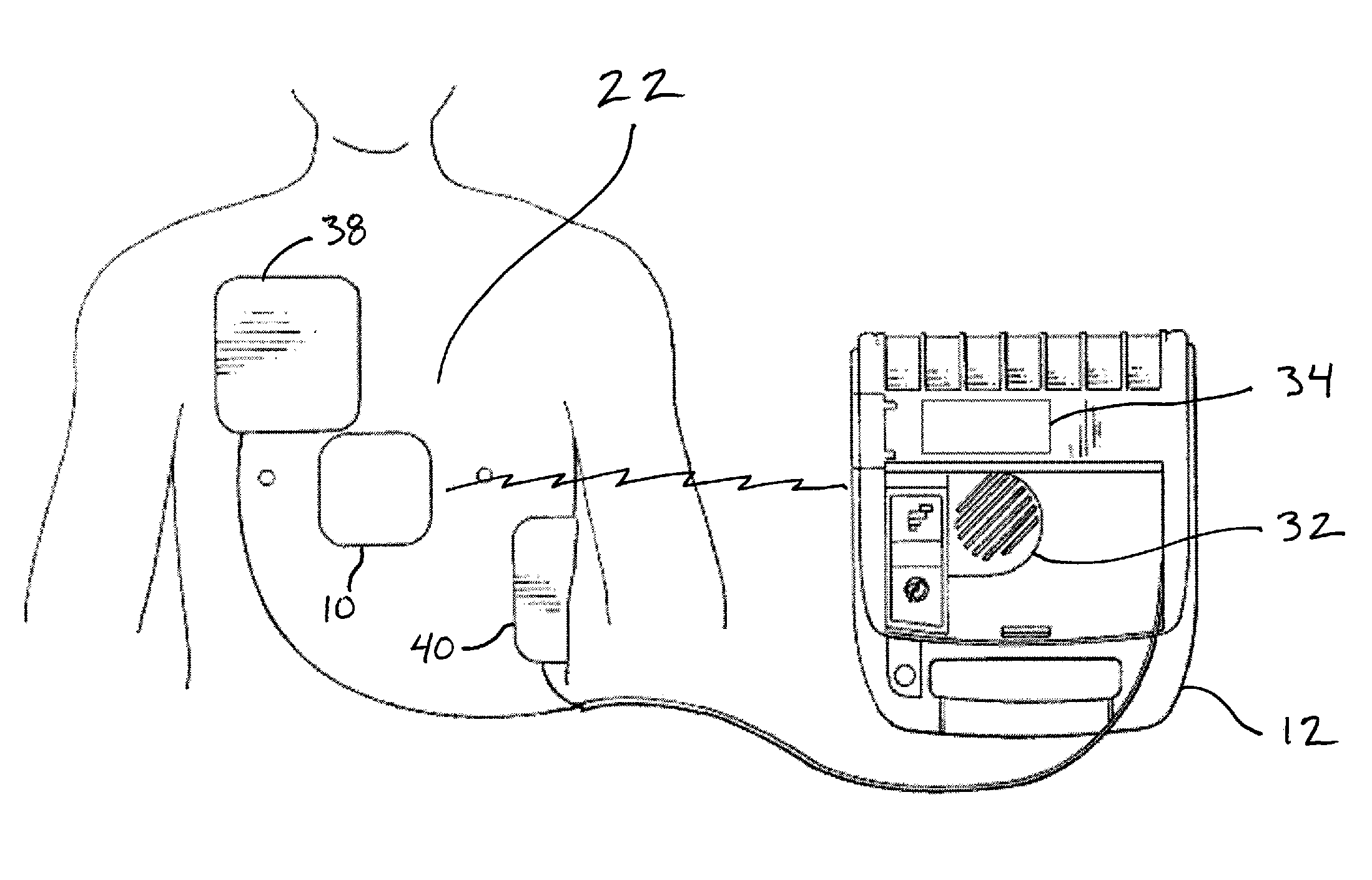
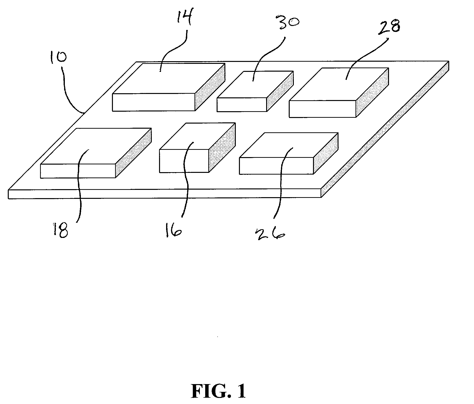
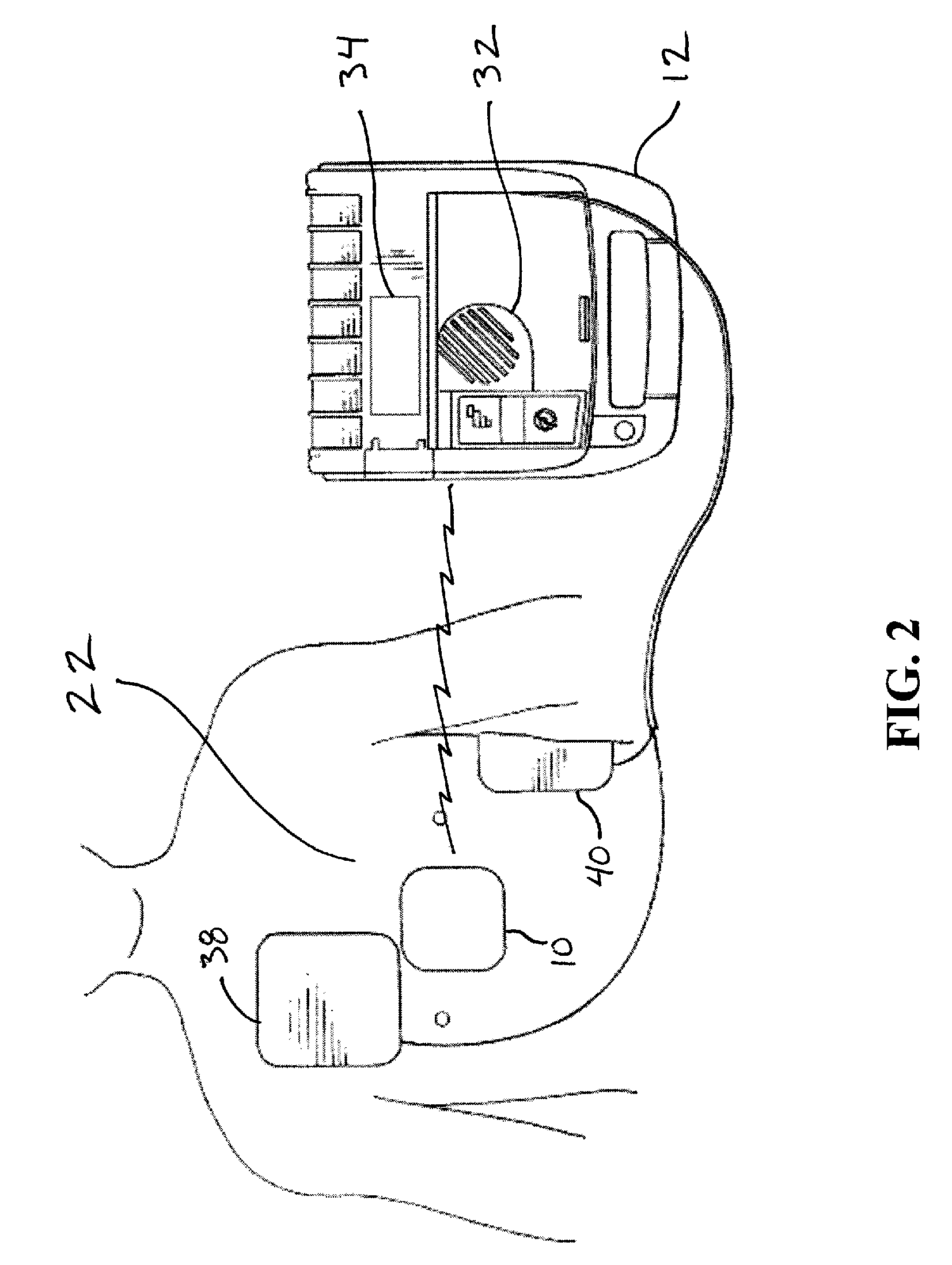
[0025]Referring to FIGS. 1-5, a chest compression detection device 10 is depicted. Device 10 includes a signal transmitter 14, a signal receiver 16, and a processor 18. In one embodiment, device 10 comprises an ultrasonic transducer. Transmitter 14 and receiver 16 are integrated into device 10. Processor 18 is operably coupled to both transmitter 14 and receiver 16. Processor 18 instructs transmitter 14 to send out an ultrasonic pulse 20, then counts the elapsed time for pulse 20 to reach receiver 16. Processor ...


PUM


Abstract

The present invention comprises a cardiopulmonary resuscitation (CPR) feedback device and a method for performing CPR. A chest compression detector device is provided that measures chest compression during the administration of CPR. The chest compression detector device comprises a signal transmitter operably positioned on the chest of the patient and adapted to broadcast a signal, and a signal receiver adapted to receive the signal. The chest compression detector device also comprises a processor, operably connected to the signal transmitter and the signal receiver. The processor repeatedly analyzes the signal received to determine from the signal a series of measurements of compression of the chest, and feedback is provided to the rescuer based on the series of measurements.

Description

FIELD OF THE INVENTION[0001]The present invention relates to devices and techniques useful for assisting in the administration of cardiopulmonary resuscitation (CPR). More particularly, the present invention relates to a device and method for using ultrasonic signals to determine the depth of chest compression during CPR.BACKGROUND OF THE INVENTION[0002]CPR is a technique used by a rescuer in an emergency situation to get oxygen into a victims blood when that persons heart has stopped beating and / or they are not breathing spontaneously. When performing CPR the rescuer creates blood circulation in the victims body by periodically compressing the victims chest.[0003]The American Heart Association (AHA) recommends that the rescuer press down on the sternum with a force sufficient to depress it between 1.5 and 2.0 inches. The current recommended rate for these periodic depressions is 100 times a minute, and 30 chest compressions should be given for every two rescue breaths. Chest compre...

Claims


Application Information

Patent Timeline
IPC IPC(8): A61H31/00A61N1/00
CPCA61H31/005A61H31/007A61H2031/002A61H2201/10A61H2201/5007A61N1/39A61H2201/5048A61H2201/5058A61H2201/5097A61H2230/00A61H2230/207A61H2201/5043A61N1/39044
Inventor OLSON, KENNETH F.PETERSON, PETER
Owner ZOLL MEDICAL CORPORATION
Why Eureka
Try Eureka