Projection apparatus
a technology of projection apparatus and holding structure, which is applied in the direction of television system, instruments, optics, etc., can solve problems such as image distortion
- Summary
- Abstract
- Description
- Claims
- Application Information
AI Technical Summary
Benefits of technology
Problems solved by technology
Method used
Image
Examples
embodiment 1
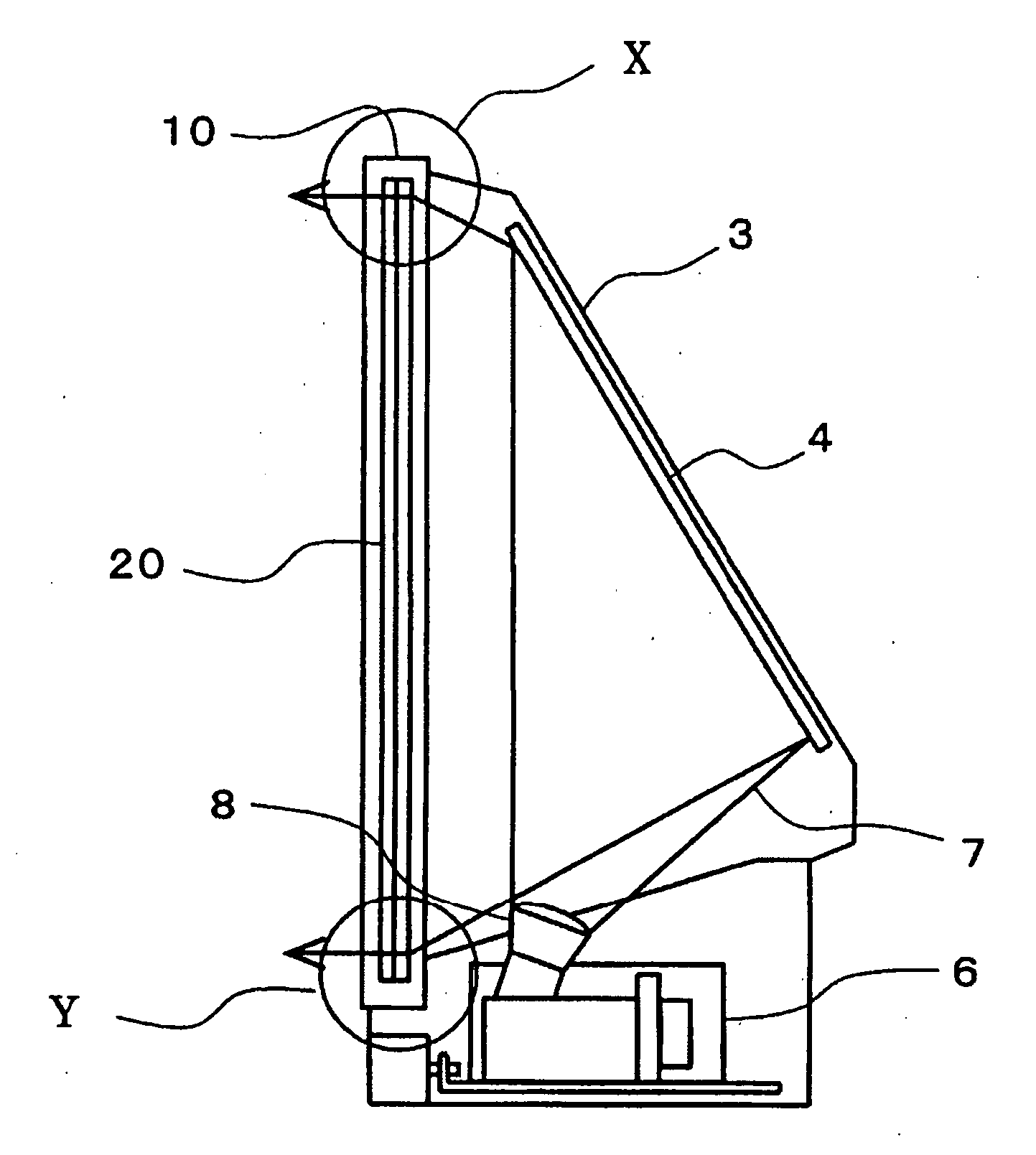
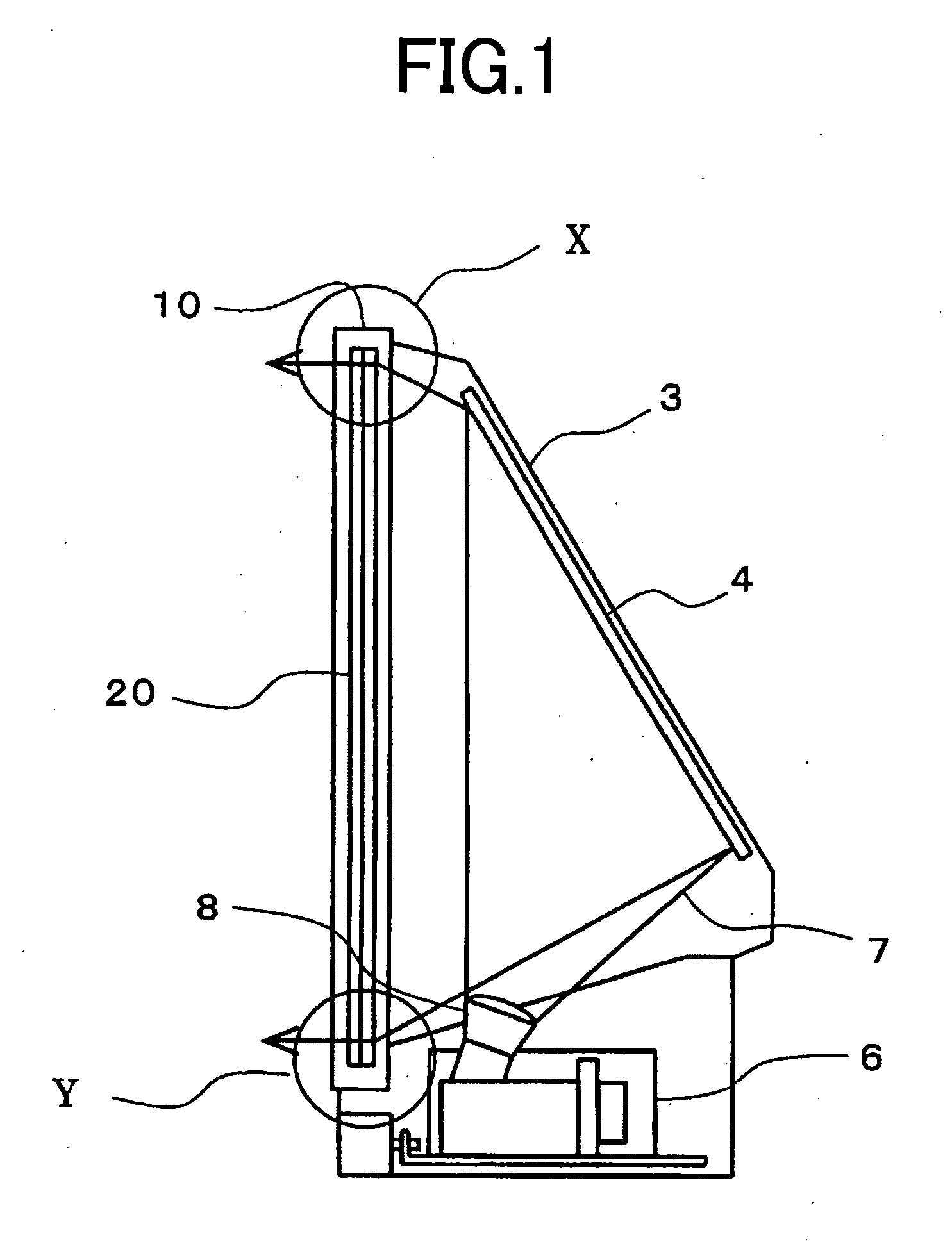
[0022]FIG. 1 is a configuration diagram illustrating a projection apparatus according to Embodiment 1 of the present invention; in FIG. 1, reference numeral 10 denotes a frame, mounted on a case 3, for holding a screen 20. Reference numeral 6 is an optical engine, mounted inside the case 3, for enlarging and projecting an image; an image 7 projected from a projection lens 8 is reflected by a mirror 4 mounted on the inner rear side of the case 3 and projected onto the rear side of the screen 20.
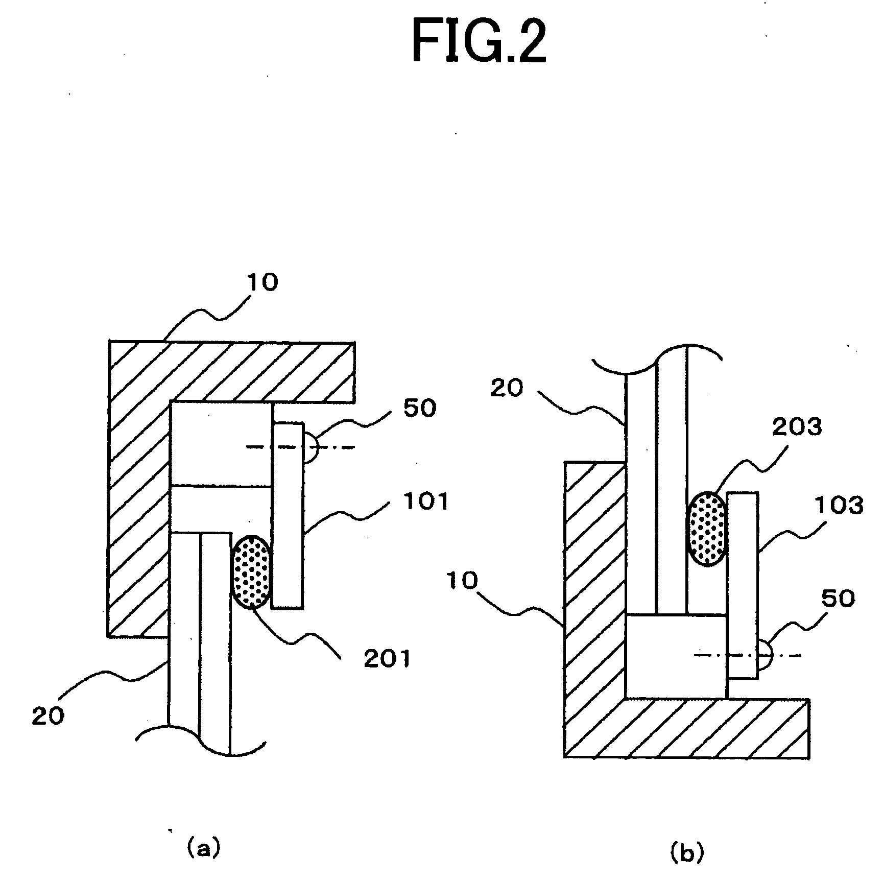
[0023] Next, the details of the fixing portion where the screen 20 is fixed in the frame 10 will be explained with reference to FIG. 2. FIGS. 2(a) and 2(b) are detailed cross-sectional views of the “X” portion (the top edge of the screen) in FIG. 1 and the ‘Y’ portion (the bottom edge of the screen) in FIG. 1, respectively. In FIG. 2(a), the screen 20 is mounted, behind the frame 10 (the right side, of the frame 10, in FIG. 2(a)), pressed and fixed by a pressure member 201 formed of an elasti...
embodiment 2
[0027] In Embodiment 1, the projection apparatus is configured in such a way that, by making the elastic force of the top-edge pressure member 201 of the screen 20 smaller than that of the bottom-edge pressure member 203, the pressing force caused by the pressure member 201 is made smaller than that by the pressure member 203, for the same bending amount; however, the projection apparatus may be configured in such a way that, by making both the elastic forces of that pressure members the same and differentiating the initial thicknesses (the dimensions in the direction which is perpendicular to the screen plane in the case where no pressing force is applied) of that pressure members, thereby differentiating the bending amounts, the pressing forces are made different.
[0028] In FIG. 4, reference numeral 211 denotes a top-edge pressure member formed in such a way as to have a thickness of L1; after the fixing member 101 fixes the top-edge pressure member 211 to the screen 20, the top-e...
embodiment 3
[0029] In Embodiment 2, the projection apparatus is configured in such a way that, by differentiating the initial thicknesses of the top-edge pressure member 211 and the bottom-edge pressure member 213, the pressing force caused by the pressure member 211 is made different from that caused by the pressure member 213; however, the projection apparatus may be configured in such a way that, by making the initial thicknesses the same and differentiating the thicknesses of the pressure members when being pressed so as to differentiate the contraction amounts, the pressing forces are made different from each other. In FIG. 6, a screen rear side 20a and a fixing member mounting surface 10a are formed in such a way as to have a dimensional difference N1. Reference numeral 221 denotes a top-edge pressure member formed in such a way as to have a thickness of L2; after the fixing member 101 fixes the top-edge pressure member 221 to the screen 20, the top-edge pressure member 221 is held compre...
PUM
 Abstract
Description
Claims
Application Information
 - R&D
- Intellectual Property
- Life Sciences
- Materials
- Tech Scout
- Unparalleled Data Quality
- Higher Quality Content
- 60% Fewer Hallucinations
Browse by: Latest US Patents, China's latest patents, Technical Efficacy Thesaurus, Application Domain, Technology Topic, Popular Technical Reports.
© 2025 PatSnap. All rights reserved.Legal|Privacy policy|Modern Slavery Act Transparency Statement|Sitemap|About US| Contact US: help@patsnap.com


