Rotary knife with blade bushing

a technology of annular blade and rotary knife, which is applied in the field of powered knives, can solve the problems of rotary knives that are problematic and suffer from certain limitations, the cutting edge of the annular blade to quickly become dull and require frequent replacement, and the non-cutting surface of the blade as well as other components of the knife is not suitable for use, so as to achieve the effect of avoiding the wear of other parts, and avoiding the wear of the blad

Active Publication Date: 2007-12-13
HANTOVER
View PDF9 Cites 73 Cited by
  • Summary
  • Abstract
  • Description
  • Claims
  • Application Information

AI Technical Summary

Problems solved by technology

Rotary knives are problematic and suffer from certain limitations.
For example, the high-speed rotational movement of the annular blade, which is ideal for quickly and efficiently processing meat, causes the cutting edge of the annular blade to quickly become dull and require frequent replacement.
Generally, the speed at which the annular blade turns also causes undesirable wear of the non-cutting surfaces of the blade as well as other components of the knife.
Rotary knives also suffer from problems associated with installation of the annular blade.
Misalignment of the blade is common, especially when blades are quickly replaced, and such misalignment generally can result in excessive wear of knife components or binding of the blade within the knife.
For this and other reasons, prior art knives are deficient at permitting quick and efficient blade replacement.
All of these problems are exacerbated by the extended and continuous period of use that is prevalent in the industry; commonly, a user will operate the same knife for an eight hour work day, five days per week.

Method used


Image

  • Rotary knife with blade bushing
  • Rotary knife with blade bushing
  • Rotary knife with blade bushing

Examples


Embodiment Construction

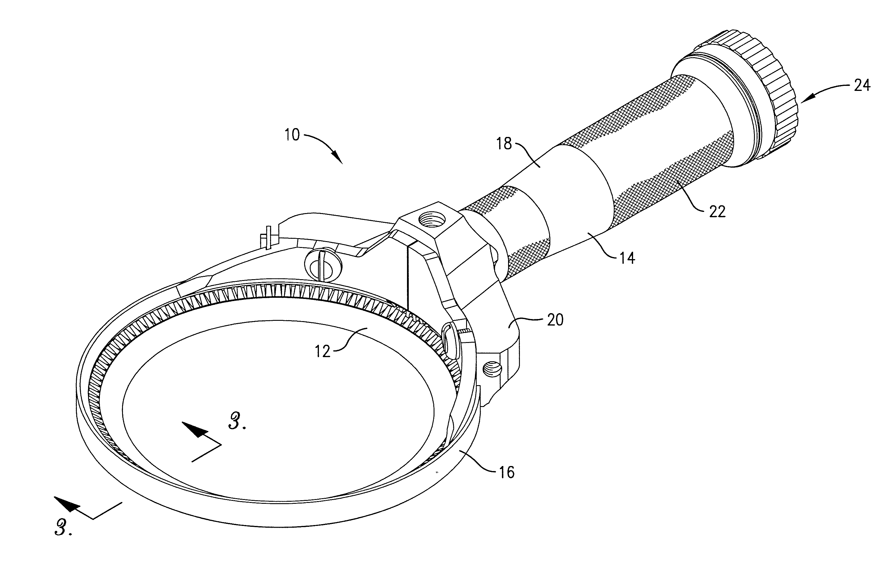
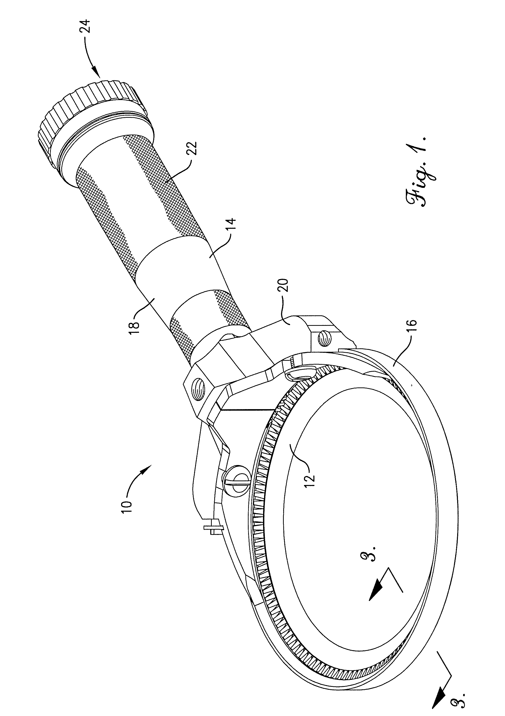
[0020] As shown in FIG. 1, the rotary knife 10 selected for illustration is particularly suitable for use in an animal slaughterhouse operation for dressing an animal carcass, although other knife applications are entirely within the ambit of the present invention. The illustrated rotary knife 10 preferably includes an annular, rotating blade assembly 12. The illustrated rotary knife 10 is preferably pneumatically powered by a pressurized air source (not shown), e.g., an air compressor. However, the principles of the present invention are equally applicable where the rotary knife is driven by alternative external power sources which transmit power through hydraulic power or electrical power. The rotary knife 10 broadly includes a handle 14, a blade housing 16, and the rotating blade assembly 12.

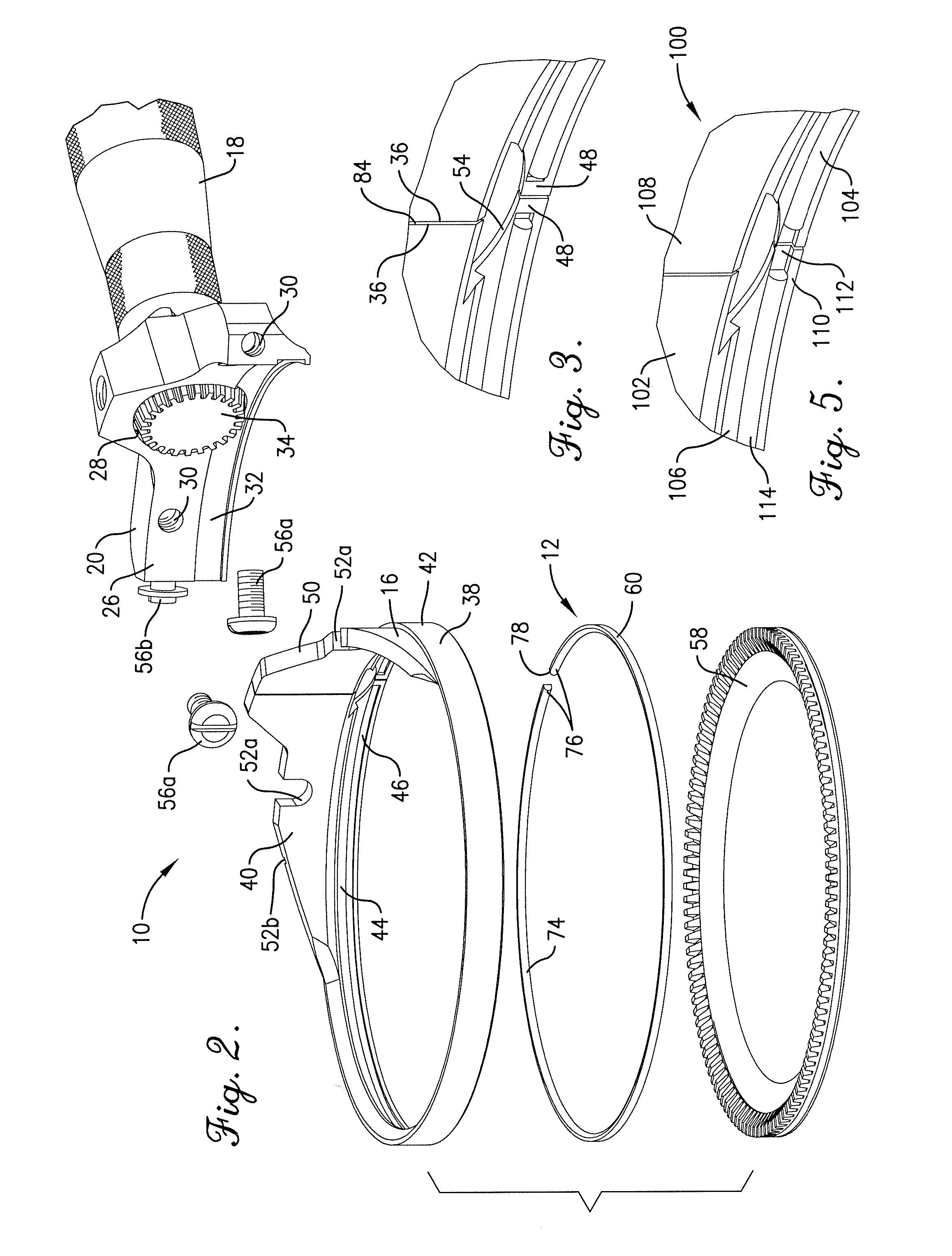
[0021] Turning to FIGS. 1 and 2, the handle 14 includes a grip housing 18 and a base 20. The grip housing 18 includes a knurled outer surface 22 for enhancing the friction between a user's h...


PUM


Abstract

A powered rotary knife includes a handle, a blade housing, an annular blade, and a blade bushing for rotatably mounting the blade within the housing. The blade housing includes an inner groove that is operable to receive the blade bushing therein. The blade housing and blade bushing are split in order to expand and receive the blade. The blade includes an outer groove that is also operable to receive the blade bushing. Thus, the blade bushing is spaced between the blade housing and blade and rotatably secures the blade within the blade housing.

Description

RELATED APPLICATION [0001] This application is a continuation-in-part of application Ser. No. 11 / 423,266 filed Jun. 9, 2006, and entitled ROTARY KNIFE WITH BLADE BUSHING, which is hereby incorporated by reference herein.BACKGROUND OF THE INVENTION [0002] 1. Field of the Invention [0003] The present invention relates generally to powered knives, such as those commonly used in slaughterhouses for meat processing. More specifically, the present invention concerns a rotary knife with a rotating annular blade and an annular bushing for supporting the blade. [0004] 2. Discussion of Prior Art [0005] Powered knifes that are used in the meat processing industry for dressing an animal carcass are known in the art. The process of dressing the carcass normally involves the removal of meat and fat from various bones as well as cutting various bones. Powered knifes enable workers to perform this process with much greater efficiency than with traditional, unpowered knives. Among these prior art po...

Claims


Application Information

Patent Timeline
Patent Type & Authority Applications(United States)
IPC IPC(8): B26B25/00B26B9/00
CPCA22B5/165B26B25/002A22B5/168A22C17/04
Inventor LEVSEN, CLARK A.
Owner HANTOVER
Why Eureka
Try Eureka