Wood stove radon reduction system

a radon reduction and wood stove technology, applied in the field of wood stoves, can solve the problems of requiring a blower, requiring maintenance and electricity, and not only the initial cost of the system, and achieve the effect of being easily adapted to a conventional wood stov

Inactive Publication Date: 2007-12-13
KILMER GEORGE
View PDF37 Cites 5 Cited by
  • Summary
  • Abstract
  • Description
  • Claims
  • Application Information

AI Technical Summary

Benefits of technology

[0011]Yet an additional object of the present invention is to provide a rado

Problems solved by technology

A blower is required adding not only to the initial cost of

Method used


Image

  • Wood stove radon reduction system
  • Wood stove radon reduction system
  • Wood stove radon reduction system

Examples


Embodiment Construction

[0020]For the purposes of promoting an understanding of the principles of the invention, reference will now be made to the embodiment illustrated in the drawings and specific language will be used to describe the same. It will nevertheless be understood that no limitation of the scope of the invention is thereby intended, such alterations and further modifications in the illustrated device, and such further applications of the principles of the invention as illustrated therein being contemplated as would normally occur to one skilled in the art to which the invention relates.

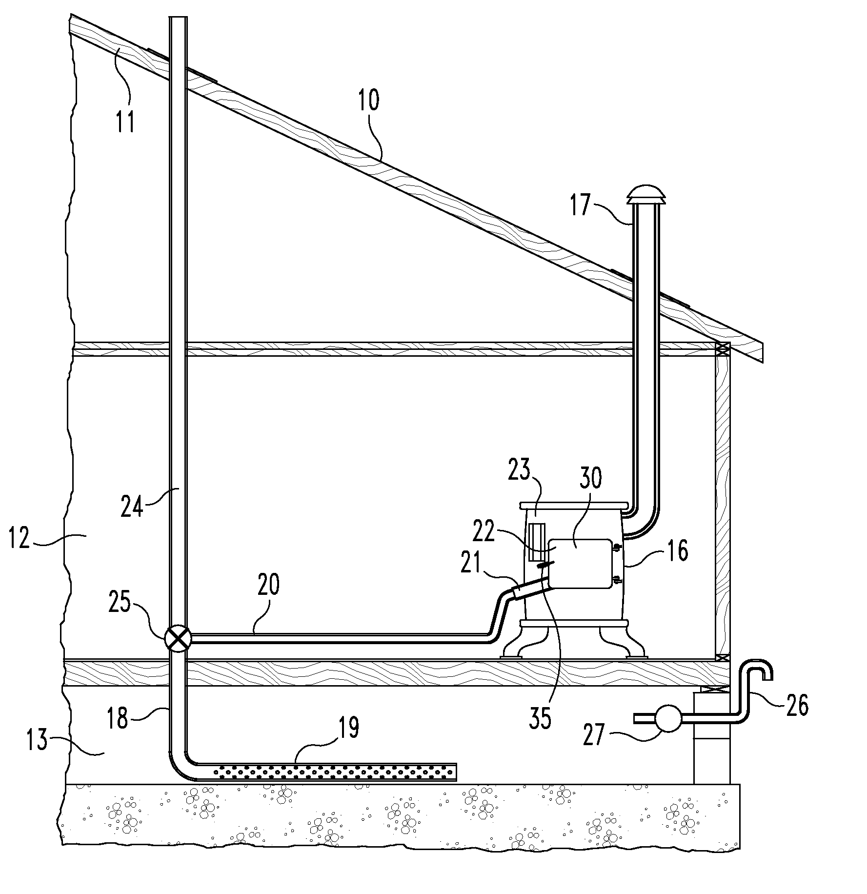
[0021]Referring now more particularly to the FIG. 1, there is shown in fragment a building 10 having a roof 11, an interior room 12, and basement 13. A wood stove 16 is positioned within room 12 and has a conventional outlet flue 17 extending through the roof 11 to allow the exhaust gases to escape the building. A radon collection system 18 is provided to collect radon gas from the basement by a perforated tube ...


PUM


Abstract

A combination of a wood stove and radon collection system. A radon collection tube location in the basement of a building is connected via conduits leading into the combustion chamber of a wood stove. Means secure the radon collection outlet to the stove between the stove door and the stove main body. Metal strips extend across gaps formed between the stove door and stove main body when the outlet is in the installed position.

Description

BACKGROUND OF THE INVENTION[0001]1. Field of the Invention[0002]The present invention relates generally to the field of wood stoves.[0003]2. Description of the Prior Art[0004]In certain areas of the country, radon collects in the basements of buildings. Typically, a blower connected to a collection tube extending outwardly from the building is operable to force the radon gas from the building. The collection tube may extend into the basement or beneath the basement or building slab. A blower is required adding not only to the initial cost of the system but also requiring maintenance and electricity. What is needed is a radon collection system that will use the heat within the heating system to force the radon from the building. Further, there is a need to combine such as system with a wood burning stove, Disclosed herein is such a combination and system.[0005]U.S. Pat. No. 4,877,182 issued to Pugh et al. discloses a typical crawl space ventilation system to eliminate radon gas from ...

Claims


Application Information

Patent Timeline
IPC IPC(8): F24C1/14F24C15/20F24C15/04
CPCF24F2003/1696F24B1/00F24F8/70Y10S454/909
Inventor KILMER, GEORGE
Owner KILMER GEORGE
Why Eureka
Try Eureka