Spinal Rod System

a spine and rod system technology, applied in the field of orthopaedic stabilization devices, can solve the problems of requiring surgical treatment, and affecting the stability of the spine, and achieves the effect of effective and adequate stabilization, simple installation and no risk of applying excessive for

Active Publication Date: 2007-12-13
LOGAN JOSEPH NICHOLAS
View PDF94 Cites 150 Cited by
  • Summary
  • Abstract
  • Description
  • Claims
  • Application Information

AI Technical Summary

Benefits of technology

[0015]It is therefore an object of the present invention to provide a spine stabilization system which is simple to install without the risk of apply

Problems solved by technology

In general, spinal column diseases often require surgical treatment when more conservative management and treatment is unsuccessful.
This removal of tissue weakens the spinal column.
As is also well known in the art, there are serious drawbacks to spinal fusion and spinal fixation techniques.
The increased movement by parts of the spine adjacent to immobilized vertebrae causes significant strain and wear on those adjacent parts.
Such strain could lead to further injury and pain.
Unfortunately, these devices have serious drawbacks.
One serious drawback is that it is often difficult to install the rod members in the bone anchors.
When the rod member is to be installed in more than one anchor, it can be difficult to orient the rod properly without damaging the rod, the bone anchors, or even the body tissues of the patient.
The prior art fails to provide pedicle screw to rod connectors that can be easily adjusted at the time of im

Method used


Image

  • Spinal Rod System
  • Spinal Rod System
  • Spinal Rod System

Examples


Embodiment Construction

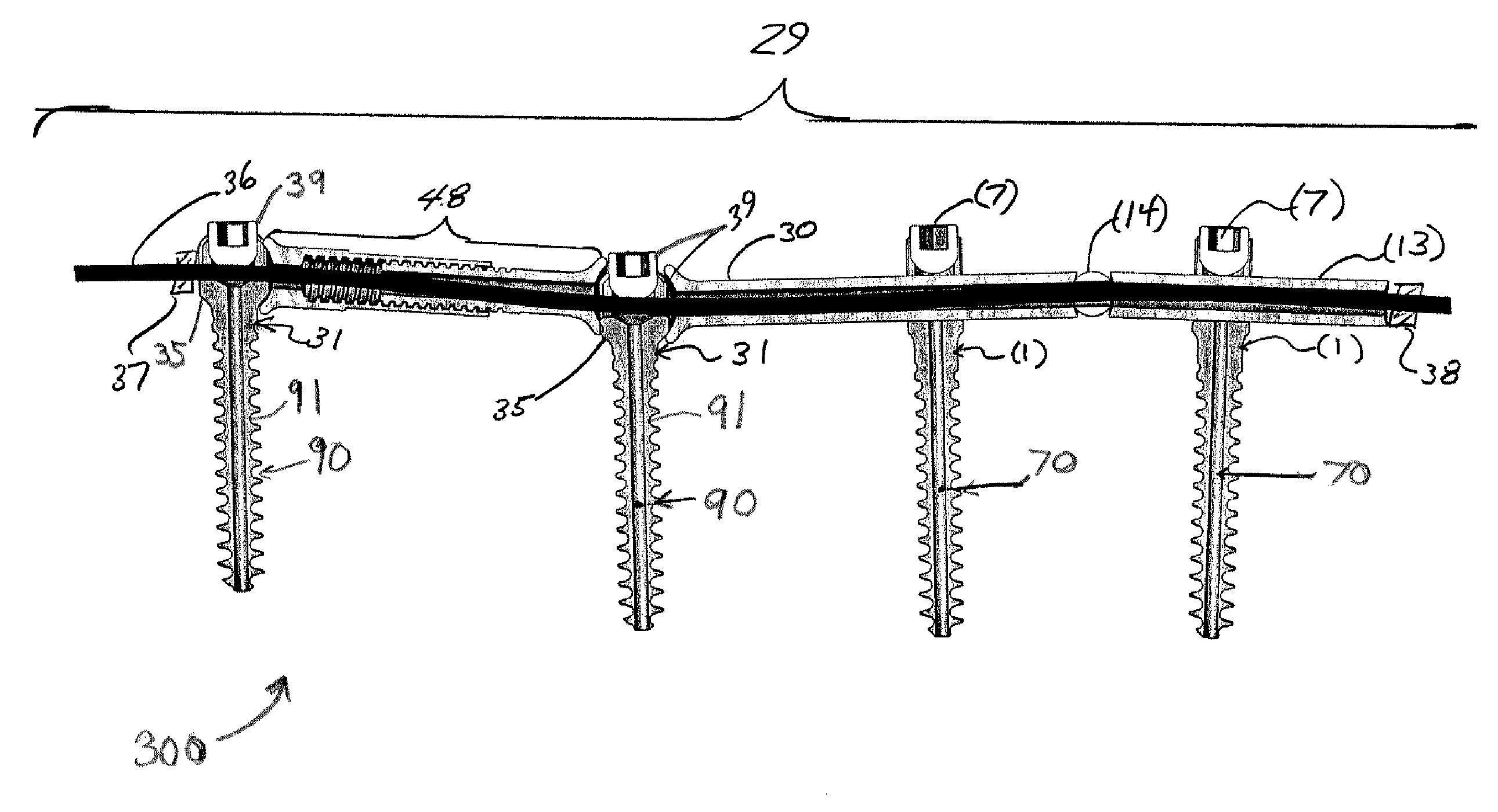
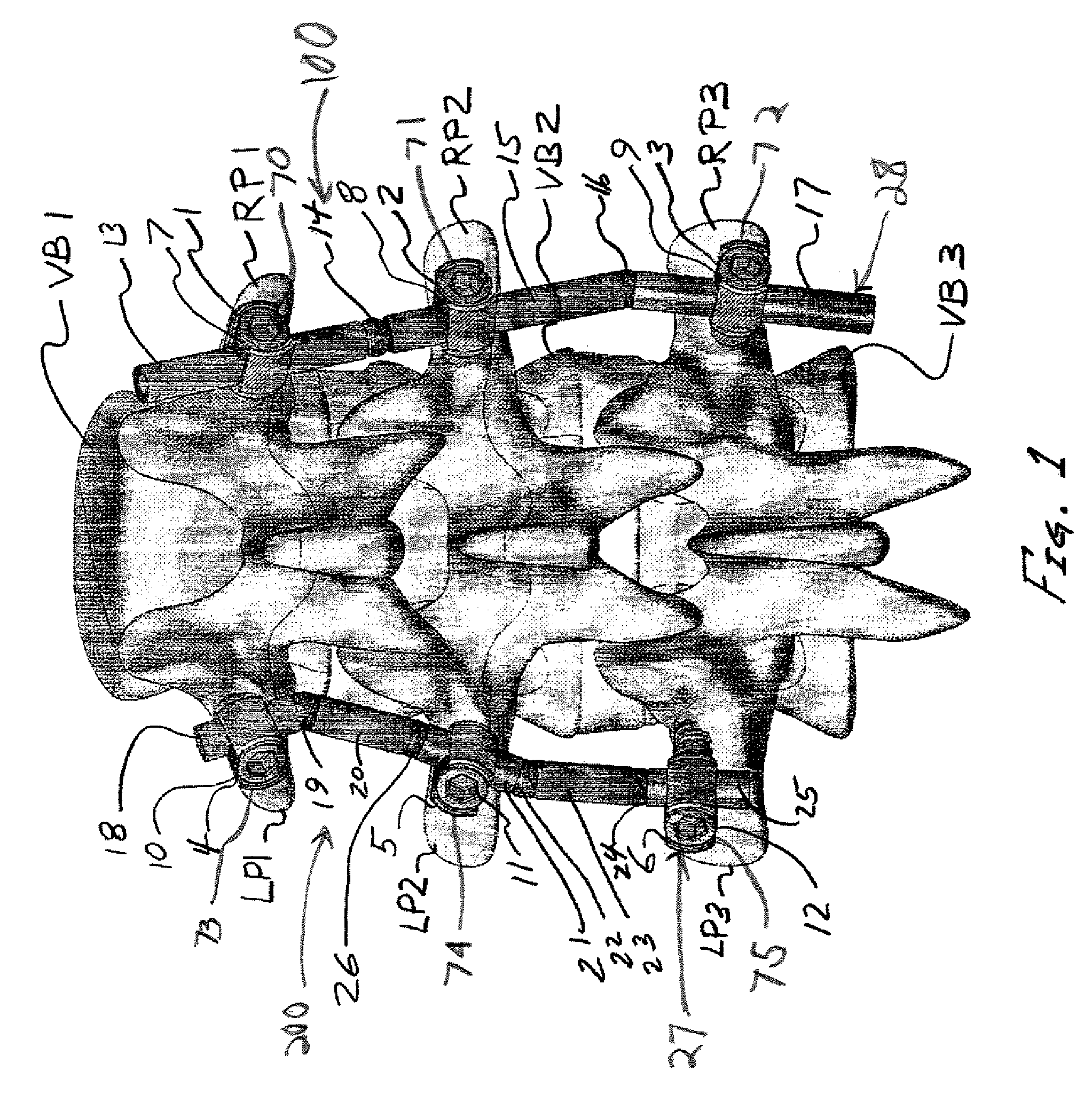
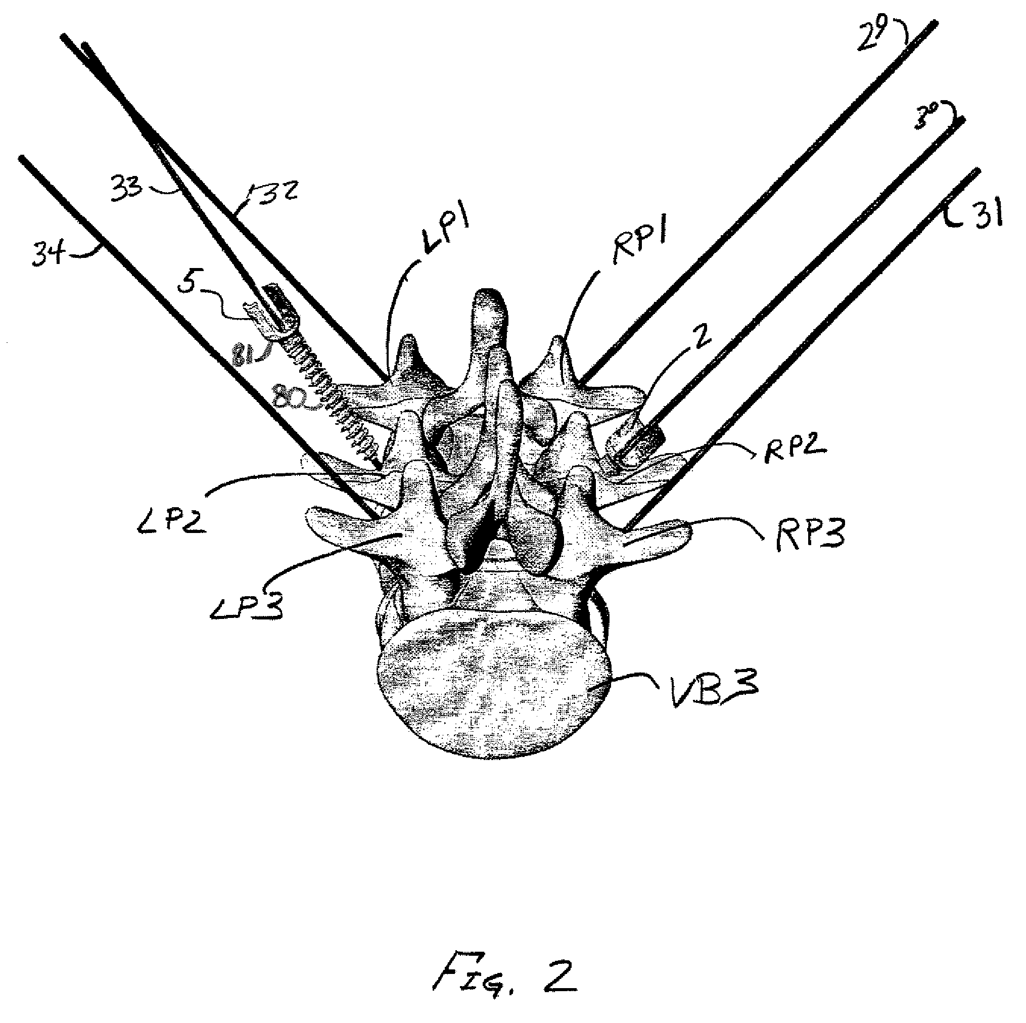
[0054]Embodiments of the present invention will now be described with reference to the accompanying drawings. FIG. 1 shows spine stabilization systems according to the present invention installed in three vertebrae of a human spine. The systems shown in FIG. 1 are rigid fixation systems which permit little to no relative movement between the relevant vertebrae. The three vertebrae VB1, VB2, and VB3 have left pedicles LP1, LP2, and LP3 and right pedicles RP1, RP2, and RP3. Spine stabilization systems 100 and 200 include the rod assemblies 27 and 28 and are secured to vertebrae VB1, VB2, and VB3 by bone anchor assemblies 70, 71, 72, 73, 74, and 75. Rod assemblies 27 and 28 are made up of rod members 13, 15, 17, 18, 20, 21, 23, and 25, pivot members 14, 16, 19, 26, 22, and 24, and a tether (not shown in FIG. 1) in each of rod assemblies 27 and 28. The bone anchor assemblies 70, 71, 72, 73, 74, and 75 comprise anchor members 1, 2, 3, 4, 5, and 6 and screw top members 7, 8, 9, 10, 11, an...


PUM


Abstract

A multi-axis spinal fixation device which can use a fixed head spinal or pedicle screw in combination with a multi-axial rod assembly to achieve anatomically correct fixation of vertebrae. The orthopedic fixation can be controlled by a different combination of rod elements to provide a varied range of motion between adjacent vertebrae as well as specific flexibility between the adjacent vertebrae or levels. The surgeon can make intra-operative adjustments from rigid fixation to dynamic stabilization and where desired also provide ‘soft-stabilization’ or ‘micro motion’. The unique combination of elements can provide fixed stabilization for the purpose of fusion or dynamic stabilization without fusion.

Description

CROSS REFERENCE TO RELATED APPLICATIONS[0001]The present application claims the benefit of priority under 35 U.S.C. §119(e) to U.S. Provisional Application No. 60 / 792,931 filed on Apr. 18, 2006, entitled “Spinal Rod System,” the entirety of which is incorporated by reference herein.FIELD OF THE INVENTION[0002]This invention relates generally to orthopedic stabilization devices and, more particularly, to a multi-axis spine stabilization system for securing vertebrae together for the purpose of fusion or dynamic stabilization without fusion.BACKGROUND OF THE INVENTION[0003]The use of fixation devices for the treatment of degenerative disc disease, vertebrae and spinal deformities and trauma is well known in the art. U.S. Pat. No. 6,966,910 to Ritland and U.S. Patent Application Publication No. 20050177157 of Jahng thoroughly describe the state of the art, the disclosures of which are incorporated by reference herein. In general, spinal column diseases often require surgical treatment ...

Claims


Application Information

Patent Timeline
IPC IPC(8): A61B17/58
CPCA61B17/7008A61B17/7011A61B17/7014A61B17/7032A61B17/7023A61B17/7031A61B17/702
Inventor LOGAN, JOSEPH NICHOLAS
Owner LOGAN JOSEPH NICHOLAS
Why Eureka
Try Eureka