Wiper Blade

Inactive Publication Date: 2007-12-20
ROBERT BOSCH GMBH
View PDF11 Cites 22 Cited by
  • Summary
  • Abstract
  • Description
  • Claims
  • Application Information

AI Technical Summary

Problems solved by technology

The disadvantage of these systems is that when the wiper strip wears out, the complete wiper blade must be replaced as a ready-made mounted

Method used


Image

  • Wiper Blade
  • Wiper Blade
  • Wiper Blade

Examples


Example

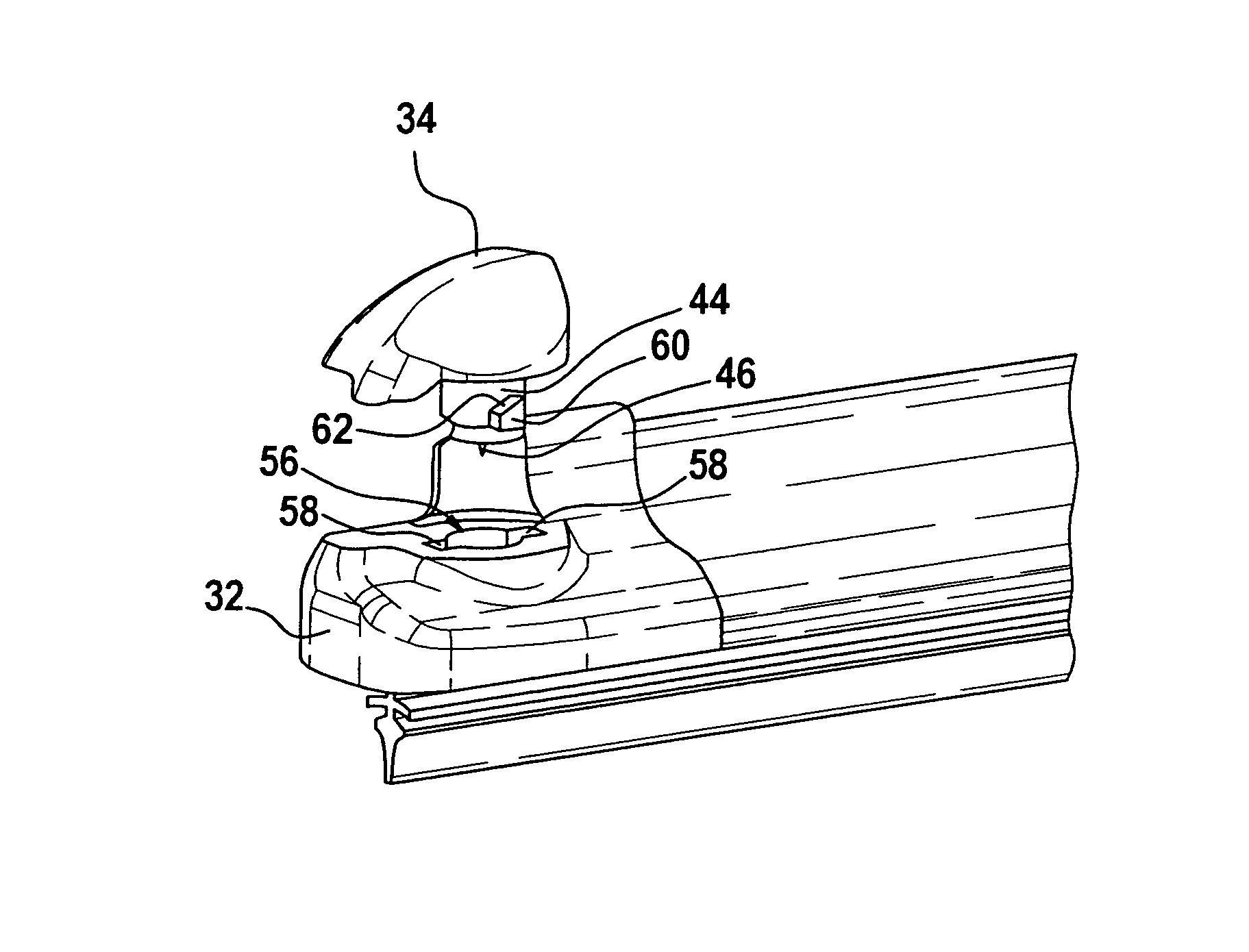
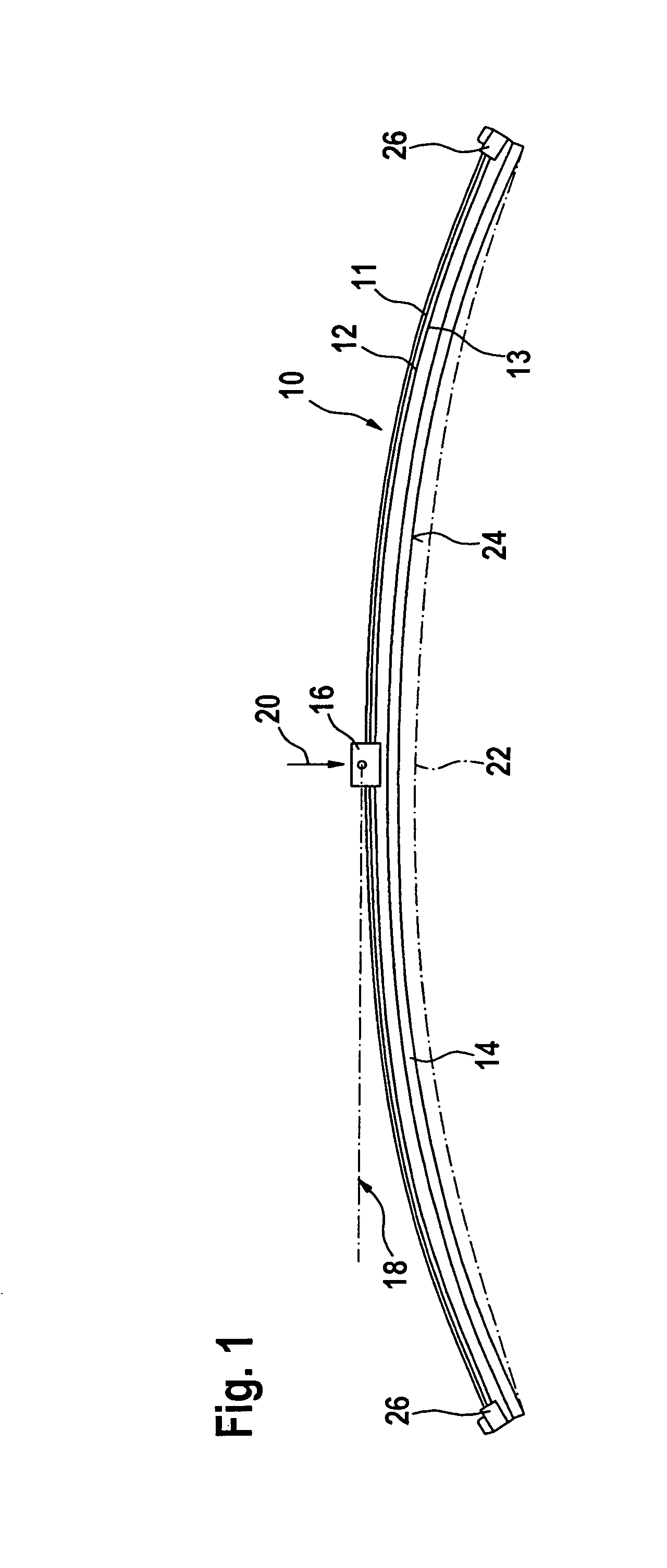
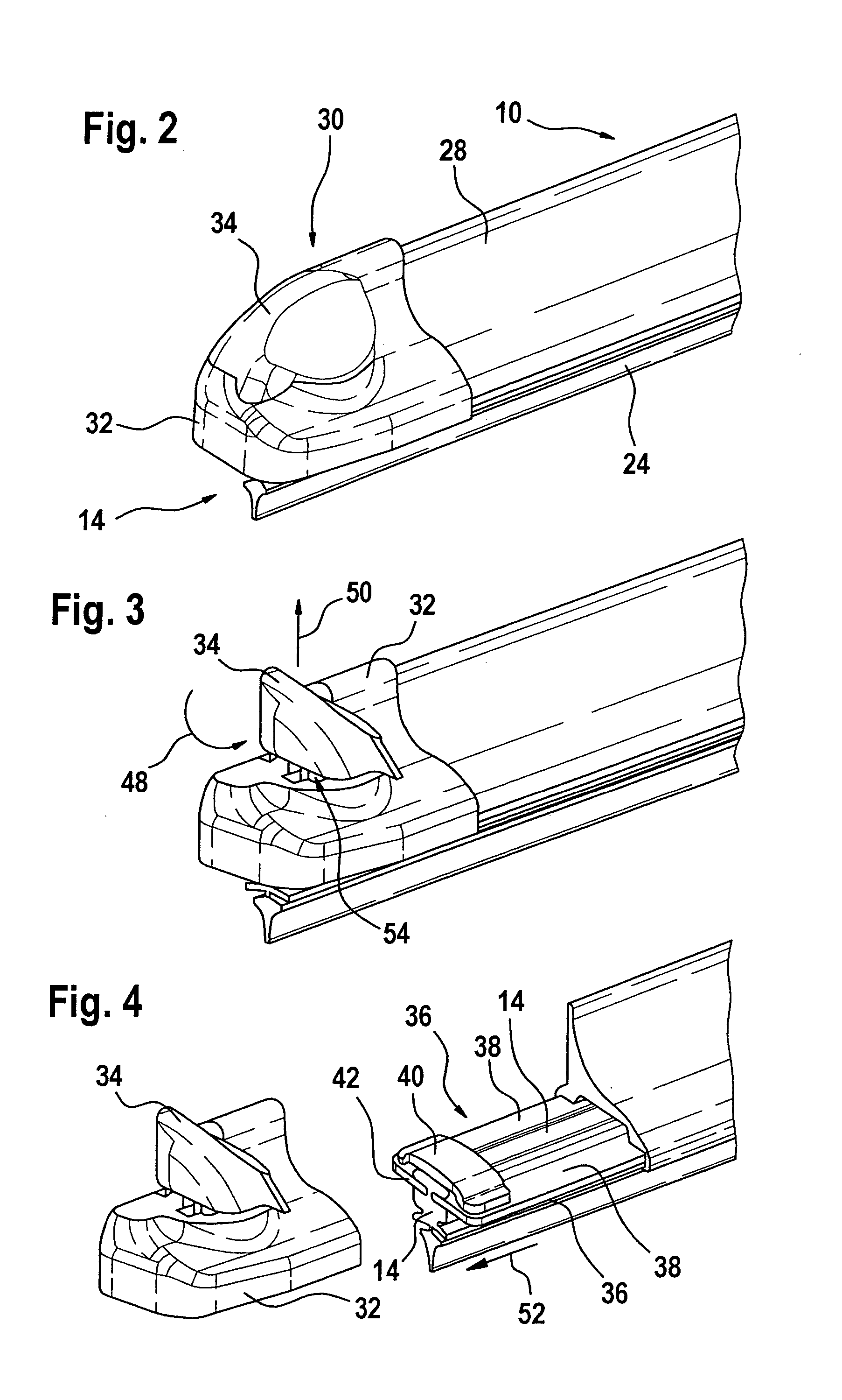
[0018] A wiper blade 10 depicted in FIG. 1 has a band-like, long-stretched-out, spring elastic supporting element 12, on whose underside 13 a long-stretched-out rubber elastic wiper strip 14 is arranged in a longitudinally axially parallel manner. Directly arranged on the upper side 11 of the supporting element 12 that can also be designated as a spring girder is the part of the connecting device 16 on the wiper blade side, with whose assistance the wiper blade 10 can be detachably connected in an articulated manner to a driven wiper arm 18 indicated in FIG. 1 by a dot-dash line. For this purpose, the wiper arm 18 is provided on its free end with the part of the connecting device on the wiper arm side. The wiper arm 18 is stressed in the direction of arrow 20 towards the to-be-wiped window, e.g., towards the windshield of a motor vehicle, whose to-be-wiped surface is indicated by a dot-dash line 22 in FIG. 1. Since the line 22 is supposed to represent the greatest curvature of the w...


PUM


Abstract

The invention relates to a wiper blade (10) comprising a supporting element (12), on whose one side a wiper strip (14) can be mounted and on whose other side a connecting device (16) for a wiper arm (18) can be mounted, and which has two longitudinal rails (38) that are fixed relative to one another via bridges (40) and covered by caps (30, 70) at their ends (42). It is proposed that at least one cap (30, 70) consist of several parts and have a basic body (32, 72) and at least one moveable part (34, 74), wherein the basic body (32, 72) establishes a connection to the longitudinal rails (38), and the moveable part (34, 74) directly and/or indirectly fixes the wiper strip (14).

Description

PRIOR ART [0001] In the case of wiper blades in accordance with the species, the supporting element is supposed to guarantee the most uniform possible distribution of the wiper blade application force originating from the wiper arm connected to a wiper blade on the windshield over the entire wiper field being covered by the wiper blade. Because of a corresponding curvature of the unstressed supporting element—i.e., when the wiper blade is not adjacent to the windshield—the ends of the wiper strip that is applied completely to the window during wiper blade operation are stressed by the then tensioned supporting element on the windshield, even though the curvature radii of spherically curved vehicle windshields change with every wiper blade position. The curvature of the wiper blade must therefore be somewhat greater than the greatest curvature measured in the wiper field on the to-be-wiped windshield. The supporting element thereby replaces the expensive supporting bracket design wit...

Claims


Application Information

Patent Timeline
IPC IPC(8): B60S1/38
CPCB60S1/38B60S1/381B60S2001/3822B60S1/3893B60S1/3891B60S1/32B60S1/04
Inventor HERINCKX, DIRKOP'T ROODT, INIGOBEELEN, HANSBAELEN, DAVID VAN
Owner ROBERT BOSCH GMBH
Why Eureka
Try Eureka