Wave relieving geometric features in structural members that are radially expandable into workpieces

a technology of geometric features and structural members, applied in the field of structural members, can solve the problems of protruding bushing ends to contact and/or damage mating parts, affecting the distribution of clamping load through the assembled members, and affecting the effect of fastener clamping

Inactive Publication Date: 2007-12-20
FATIGUE TECH
View PDF99 Cites 38 Cited by
  • Summary
  • Abstract
  • Description
  • Claims
  • Application Information

AI Technical Summary

Benefits of technology

[0019] In still yet another aspect, a method of manufacturing a structural member to be secured into an opening of a workpiece, the method includes forming an outer surface and an inner surface, the outer surface radially offset from the inner surface to form a wall of the structural member; forming first end and a second end opposite the first end; forming a first face at the first end and a second face at the second end, the inner surface extending between the first and the second ends to form a longitudinally-extending passage therebetween; and forming a recess into at least one of either the first face or the second face, wherein the recess defines a volume sized to accommodated a first amount of upset material expected when an expansion mandrel is passed through the longitudinally-extending passage during a radial expansion process to secure the structural member into the opening of the workpiece.

Problems solved by technology

Installation of conventional bushings has been known to produce a certain amount of extruded material, upset material, and / or distorted material, near at least one end of the bushing.
If a bushing were to be installed in an over-flush or protruding condition relative to the workpiece surface, such a condition may cause the protruding bushing end to contact and / or damage a mating part.
In addition, such an over-flush bushing condition may adversely alter the fastener clamp-up load distribution through the assembled members.
Such an altered load path is typically undesirable, and may lead to structural joint problems after the airplane is in service.
In turn, this may add significant time and cost to the overall assembly, as well as increase the risk of damaging the overall assembly, which may be nearly complete.
The large force often results in a greater amount of bushing material being upset and may also result in the formation of a substantially large extrusion or growth from at least one end of the bushing.
Additionally, or alternatively, the extrusion or growth may not be uniform across the non-flanged end of the bushing where, for example, the majority of the growth occurs in an area adjacent to the inner surface of the bushing.
This type of bushing growth makes it difficult to keep the entire bushing end surface flush or under-flush relative to the workpiece surface during installation of the bushing.
Consequently, conventional bushings may not adequately and repeatedly meet certain quality and / or aerodynamic requirements or specifications.

Method used


Image

  • Wave relieving geometric features in structural members that are radially expandable into workpieces
  • Wave relieving geometric features in structural members that are radially expandable into workpieces
  • Wave relieving geometric features in structural members that are radially expandable into workpieces

Examples


Embodiment Construction

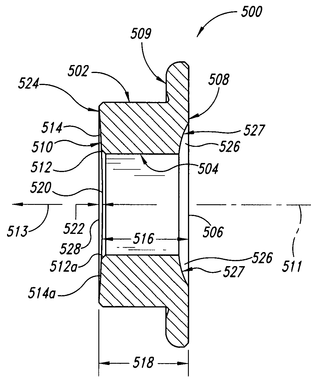
[0032] In the following description, certain specific details are set forth in order to provide a thorough understanding of various disclosed embodiments. However, one skilled in the art will understand that the embodiments may be practiced without these details. In other instances, well-known structures and methods associated with cold working and / or installing a structural member into an opening in a workpiece may not be shown or described in detail to avoid unnecessarily obscuring descriptions of the disclosed embodiments. The structural member can be a bushing, sleeve (including a split sleeve), liner, shank, rivet, or other similar component. It is appreciated and understood that the process of installing the component into the opening of the workpiece may or may not result in the creation of a zone of residual compressive stress (e.g., an annular zone of compressive stresses) in the workpiece or workpieces.

[0033] In the following description and for purposes of brevity, refer...


PUM

PropertyMeasurementUnit
lengthaaaaaaaaaa
volumeaaaaaaaaaa
residual compressive stressesaaaaaaaaaa

Abstract

A bushing with wave relieving geometric features includes a unique geometric end feature such as a countersink or arcuate surface, which creates a pocket, volume, and/or reservoir, to receive an amount of material that is extruded in a longitudinal direction during radial expansion of the bushing. At the mandrel exit side of the bushing, the extruded material may be accumulated from a propagating wave of material preceding a radial-expansion mandrel. At the mandrel entry side of the bushing, the extruded material may be caused by the radial force of the expansion mandrel near the unrestrained end surface at the entry side of the bushing. The unique geometric end features of the bushing may also include a high portion on the end surface of the bushing to direct the fastener clamp-up loads through the radial flange of the bushing and into the workpiece.

Description

CROSS-REFERENCE TO RELATED APPLICATION [0001] This application claims the benefit under 35 U.S.C. § 119(e) of U.S. Provisional Patent Application No. 60 / 795,888 filed Apr. 27, 2006, which is incorporated herein by reference in its entirety.BACKGROUND [0002] 1. Field of Disclosure [0003] This disclosure generally relates to a structural member, such as a bushing, having geometrical features that may reduce surface upset at the ends of the member when the member is radially expanded into a workpiece. [0004] 2. Description of the Related Art [0005] Conventional structural members, which may be hollow members such as bushings, with or without a radial flange, liners, sleeves, tubes, pipes, etc. are commonly installed into openings of workpieces for a variety of reasons. Bushings, for example, may be installed in the workpiece to reinforce and / or structurally support the region around the opening. In addition, the radial flange of the bushing may function as a washer to transmit the fast...

Claims


Application Information

Patent Timeline
Patent Type & Authority Applications(United States)
IPC IPC(8): B21D39/08
CPCF16B4/004B23P9/025
Inventor GLENN, DOUGLAS W.
Owner FATIGUE TECH
Why Eureka
Try Eureka