Image forming apparatus and fixing device

Active Publication Date: 2007-12-20
RICOH KK
View PDF22 Cites 209 Cited by
  • Summary
  • Abstract
  • Description
  • Claims
  • Application Information

AI Technical Summary

Problems solved by technology

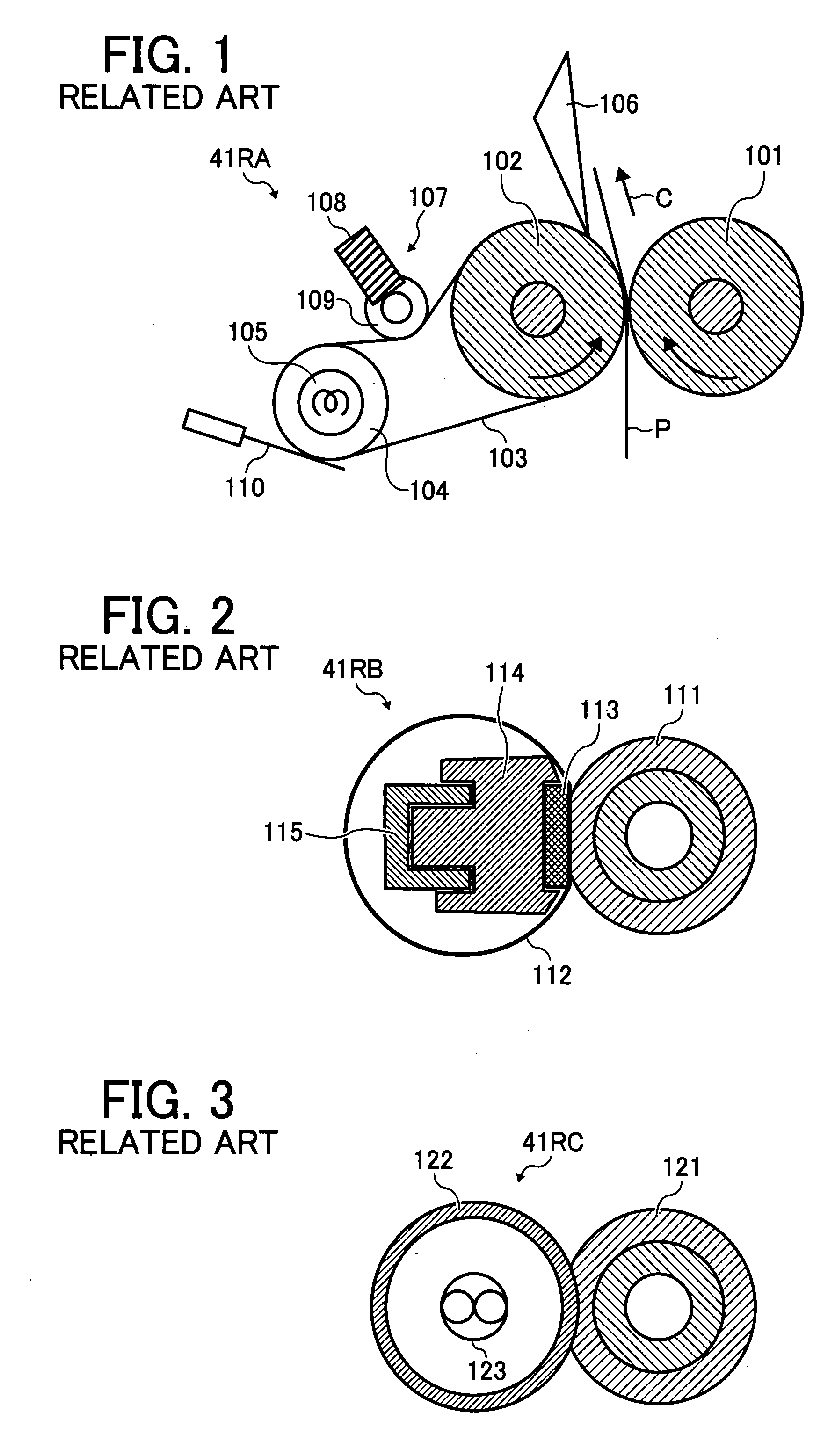
Therefore, an increased amount of heat may be radiated at a portion of the fixing belt 103 other than the nip, resulting in faulty fixing.
Heat is easily drawn from the fixing belt 112 to a sheet bearing a

Method used


Image

  • Image forming apparatus and fixing device
  • Image forming apparatus and fixing device
  • Image forming apparatus and fixing device

Examples


Embodiment Construction

[0046]It will be understood that if an element or layer is referred to as being “on”, “against”, “connected to”, or “coupled to” another element or layer, then it can be directly on, against, connected or coupled to the other element or layer, or intervening elements or layers may be present. In contrast, if an element is referred to as being “directly on”, “directly connected to”, or “directly coupled to” another element or layer, then there are no intervening elements or layers present. Like numbers refer to like elements throughout. As used herein, the term “and / or” includes any and all combinations of one or more of the associated listed items.

[0047]Spatially relative terms, such as “beneath”, “below”, “lower”, “above”, “upper”, and the like, may be used herein for ease of description to describe one element or feature's relationship to another element(s) or feature(s) as illustrated in the figures. It will be understood that the spatially relative terms are intended to encompas...


PUM


Abstract

An image forming apparatus includes an image forming device for forming a toner image on a recording medium and a fixing device for fixing the toner image formed on the recording medium by applying heat and pressure to the recording medium. In the fixing device, an endless belt, having flexibility, moves to apply heat to the recording medium. A metal thermal conductor, having a pipe shape and provided inside a loop formed by the endless belt, guides the moving endless belt. A heat source heats the metal thermal conductor. A pressing member presses the metal thermal conductor via the endless belt to form a nip between the endless belt and the pressing member. At the nip, the endless belt and the pressing member nip the recording medium bearing the toner image to apply heat and pressure to the recording medium.

Description

PRIORITY STATEMENT[0001]The present patent application claims priority of Japanese Patent Application No. 2006-168628 filed on Jun. 19, 2006 in the Japan Patent Office, the entire contents of which are incorporated by reference herein.BACKGROUND[0002]1. Technical Field[0003]Some example embodiments generally relate to an image forming apparatus and / or a fixing device, for example, for fixing a toner image on a recording medium.[0004]2. Description of Background Art[0005]A background image forming apparatus, for example, a copying machine, a facsimile machine, a printer, or a multifunction printer having copying, printing, scanning, and facsimile functions, forms a toner image on a recording medium (e.g., a sheet) according to image data by an electrophotographic method. For example, a charger charges a surface of an image carrier (e.g., a photoconductor). An optical writer emits a light beam on the charged surface of the photoconductor to form an electrostatic latent image on the ph...

Claims


Application Information

Patent Timeline
IPC IPC(8): G03G15/20
CPCG03G15/2064G03G2215/2035G03G2215/2016
Inventor SHINSHI, AKIRA
Owner RICOH KK
Why Eureka
Try Eureka