LED device having a top surface heat dissipator

Inactive Publication Date: 2007-12-27
AVAGO TECH WIRELESS IP SINGAPORE PTE
View PDF6 Cites 33 Cited by
  • Summary
  • Abstract
  • Description
  • Claims
  • Application Information

AI Technical Summary

Problems solved by technology

Despite typical design features of LED devices including those summarized above, LED devices are commonly prone to damage caused by buildup of heat generated from within the devices.
Although metallized LED substrates are useful design elements that can be incorporated in LED devices and can serve to dissipate heat, these elements are often inadequate to maintain reasonably moderate temperatures in the devices.
Excessive heat buildup can cause deterioration of c

Method used


Image

  • LED device having a top surface heat dissipator
  • LED device having a top surface heat dissipator
  • LED device having a top surface heat dissipator

Examples


Embodiment Construction

[0014]In the following description of various implementations, reference is made to the accompanying drawings that form a part of this disclosure, and which show, by way of illustration, specific implementations in which the invention may be practiced. Other implementations may be utilized and structural changes may be made without departing from the scope of the present invention.

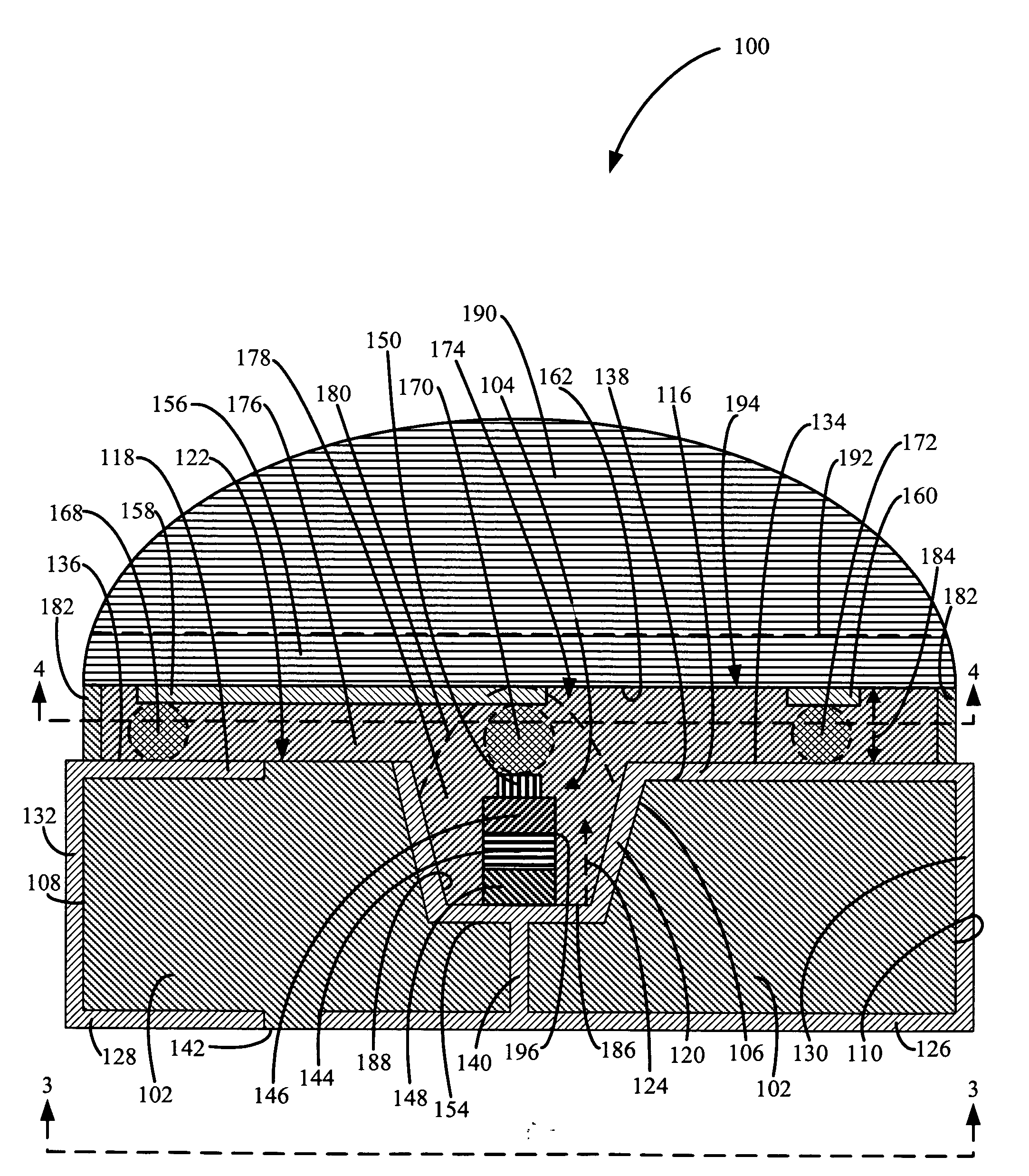
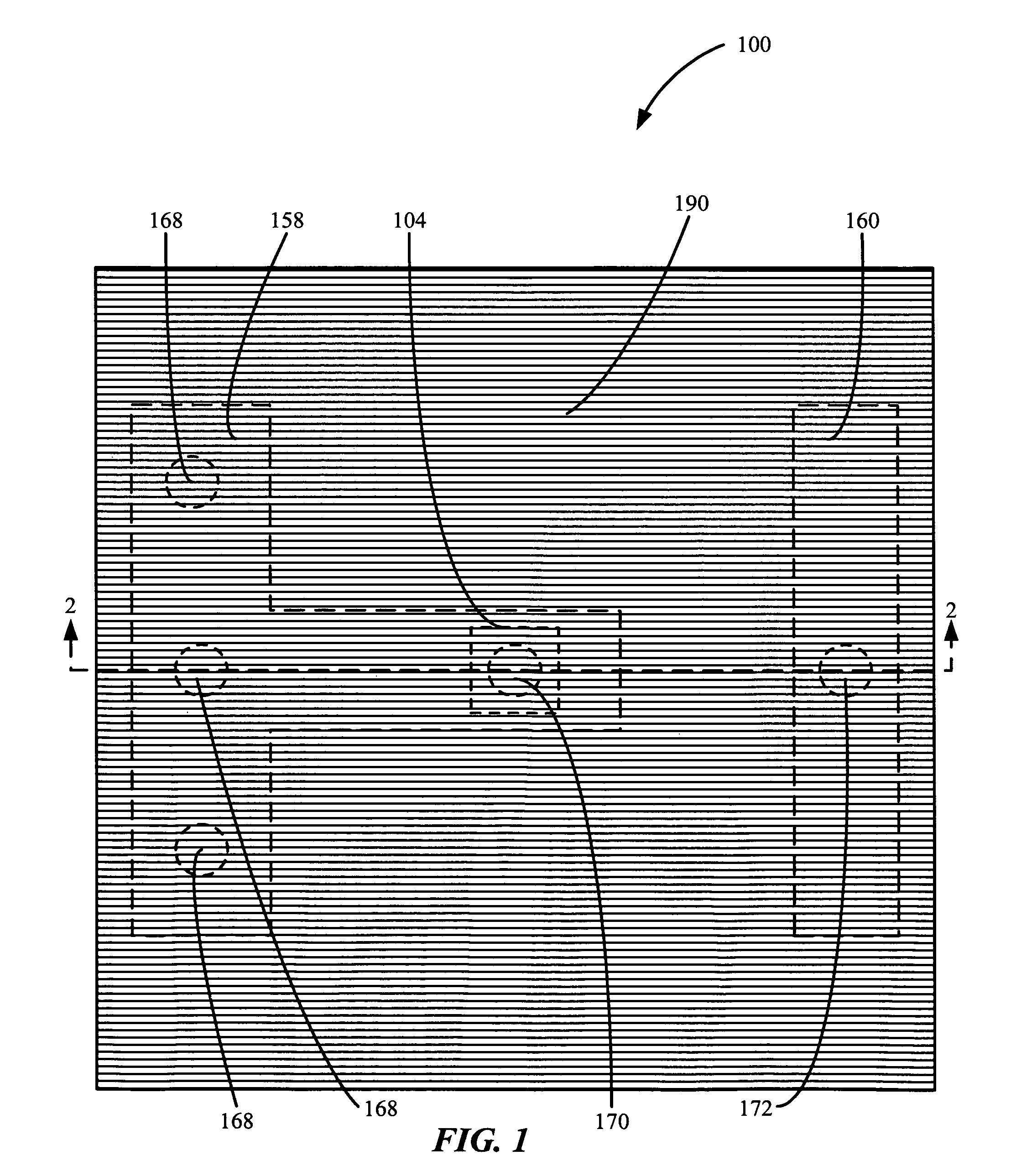
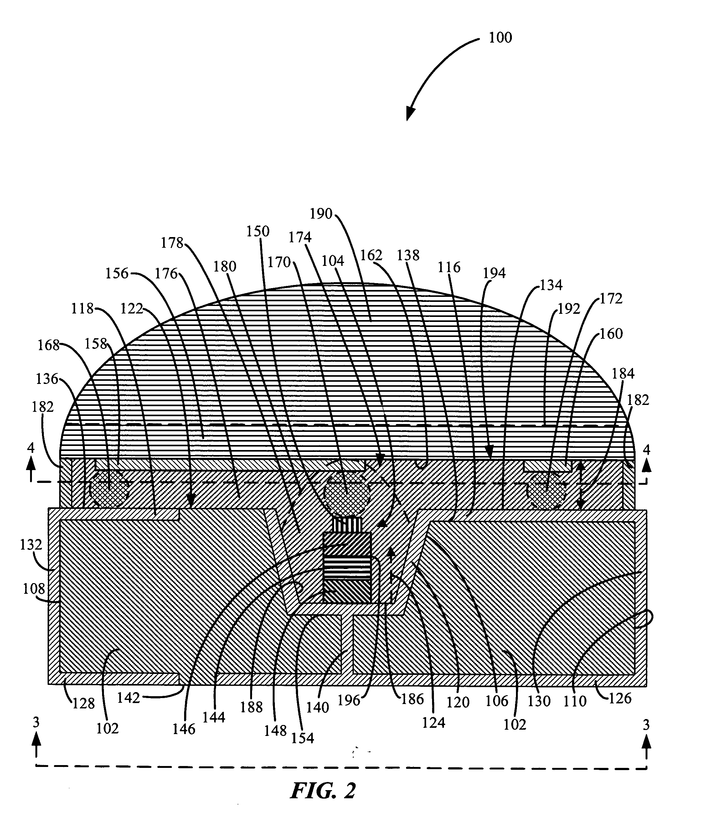
[0015]FIG. 1 is a top view showing an example of an implementation of an LED Device Having a Top Surface Heat Dissipator 100. FIG. 2 is a cross-sectional view, taken on line 2-2, showing the LED Device Having a Top Surface Heat Dissipator as shown in FIG. 1. FIG. 3 is a bottom view, taken on line 3-3, showing the LED Device Having a Top Surface Heat Dissipator shown in FIG. 1. FIG. 4 is a bottom view, taken on line 4-4, showing a Top Surface Heat Dissipator including an optically transparent body and two electrically and thermally conductive heat dissipators in the LED Device Having a Top Surface Heat Diss...


PUM


Abstract

An LED Device Having a Top Surface Heat Dissipator is provided. The LED Device Having a Top Surface Heat Dissipator includes a substrate body, and a light emitting diode over the substrate body. The LED Device Having a Top Surface Heat Dissipator also has an electrically and thermally conductive heat dissipator over the substrate body. A method of dissipating heat from an LED device is also provided.

Description

BACKGROUND OF THE INVENTION[0001]Light emitting diode (“LED”) devices are useful for generating light output. LED devices may convert electricity into photonic emissions in the form of visible light more efficiently than can incandescent and fluorescent bulbs, and can be individually configured to generate light emissions at one or more pre-selected wavelengths or wavelength bands. An LED may be positioned in a concave base housing adapted to provide an initial focus for the light output from the LED. The LED can be provided with anode and cathode interconnections placing the LED in communication with an electrical circuit for supplying a bias voltage to the LED. The LED can be encapsulated in a composition intended to protect the LED from external contaminants and from being physically damaged or dislodged, and which can form part of a lens system for further focusing the light output of the LED. A substrate on which the LED rests can include a metallized portion underneath the LED...

Claims


Application Information

Patent Timeline
IPC IPC(8): H01L33/00H01L33/58H01L33/62H01L33/64
CPCH01L33/486H01L33/58H01L33/62H01L33/642H01L2924/0002H01L33/647H01L2924/00
Inventor CHEW, TONG-FATTNG, KEE-YEAN
Owner AVAGO TECH WIRELESS IP SINGAPORE PTE
Why Eureka
Try Eureka