Adhesive tape joining apparatus

Inactive Publication Date: 2008-01-03
NITTO DENKO CORP
View PDF1 Cites 2 Cited by
  • Summary
  • Abstract
  • Description
  • Claims
  • Application Information

AI Technical Summary

Benefits of technology

[0009]The present invention has been made taking the foregoing problems into consideration and an object of which is to provide an adhesive tape joining apparatus that can carry out adhesive tape joining operation lightly and promptly by stably pressing a joining roller against a joining face of a workpiece.

Problems solved by technology

In such a state, pressure of the joining roller with respect to the joining face runs short and this causes a defective joining.

Method used


Image

  • Adhesive tape joining apparatus
  • Adhesive tape joining apparatus
  • Adhesive tape joining apparatus

Examples


Embodiment Construction

[0044]Hereinafter, an embodiment of the present invention will be described with reference to the drawings.

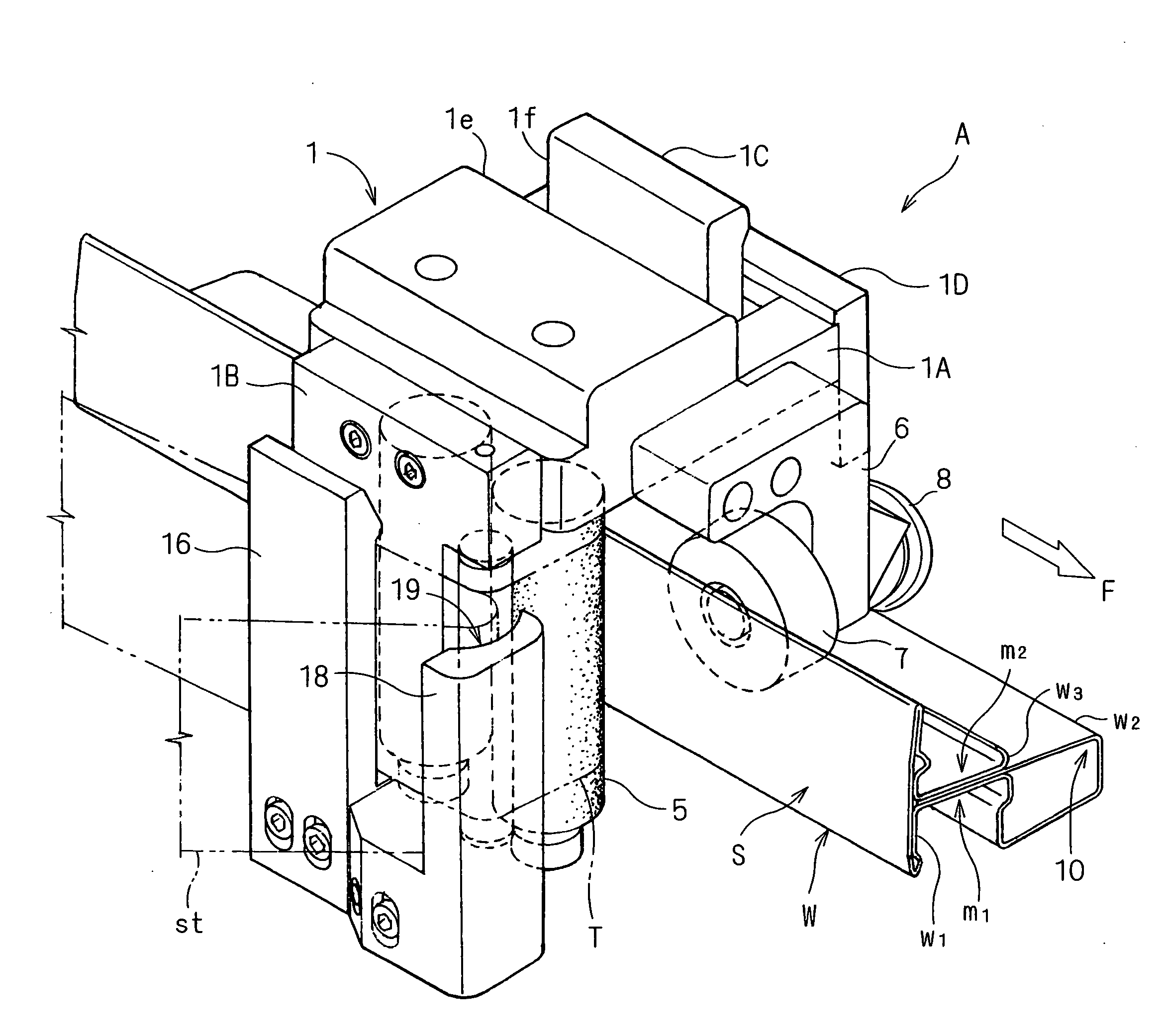
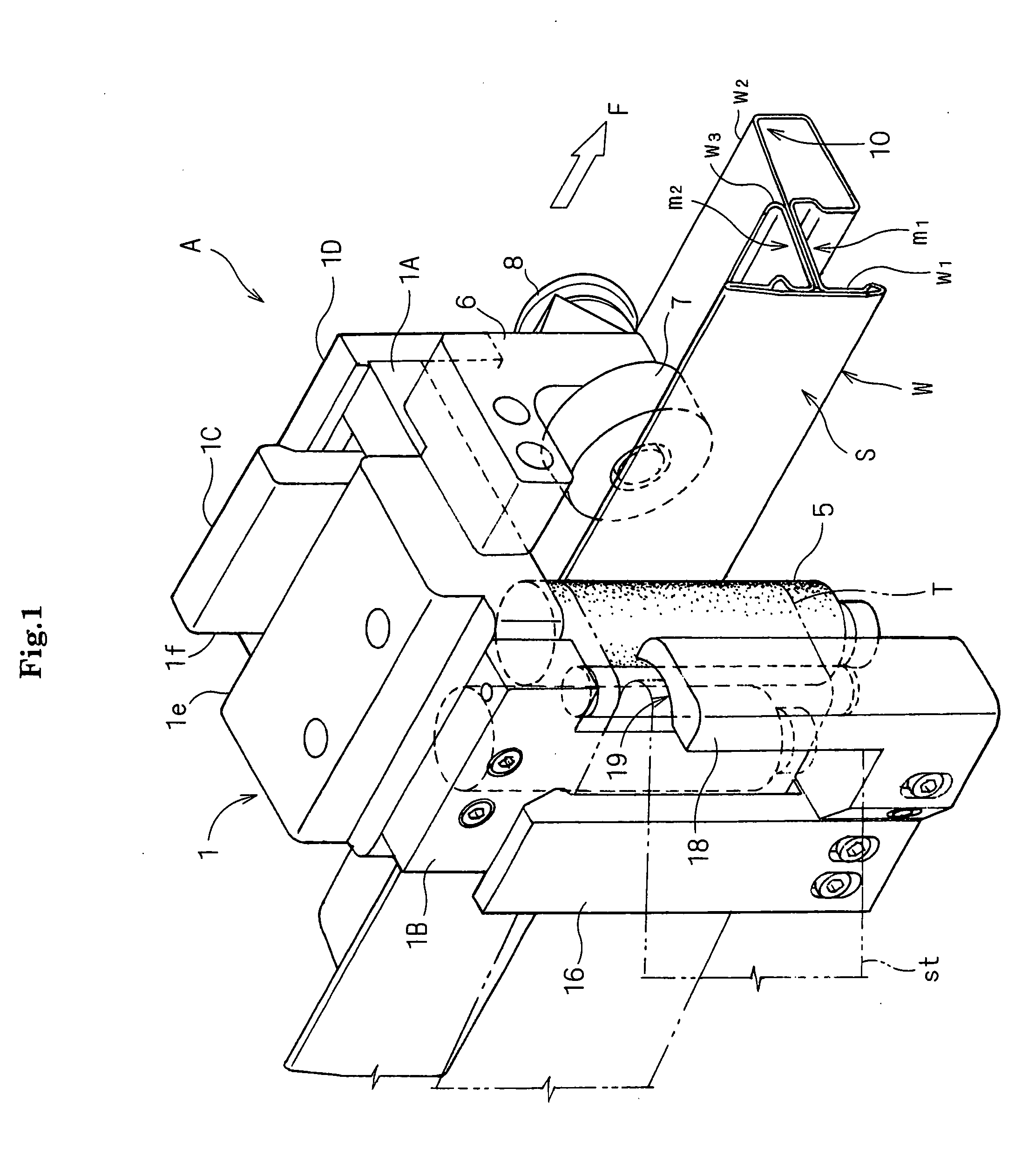
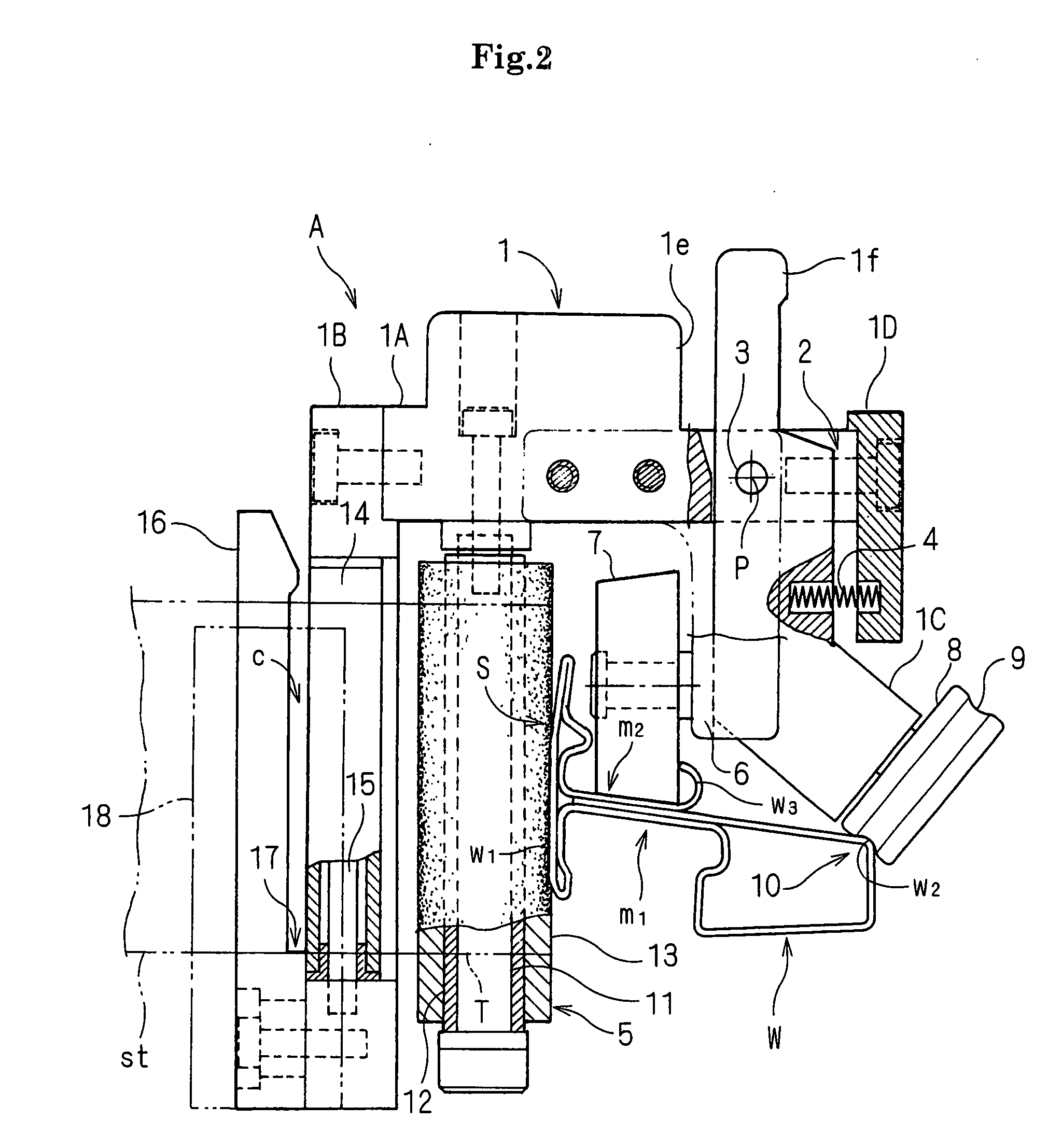
[0045]FIG. 1 is a perspective view of an adhesive tape joining apparatus A which is mounted on a workpiece, FIG. 2 is a front view of the adhesive tape joining apparatus A which is mounted on the workpiece, and FIG. 3 is a perspective view of the adhesive tape joining apparatus A seen from the opposite side.

[0046]Further, a workpiece W according to the present embodiment is a door sash of an automobile, and a black adhesive tape is joined to the outer side face of the workpiece W in place of black coating.

[0047]The workpiece W is configured by press polymerization of a single steel plate. This workpiece W has an outer frame w1 shaped in a longitudinal wall at the lateral outside that is the outer face of the door of the work W, and the workpiece W is formed with a cross section that a hollow lateral frame w2 thrusting from this outer frame w1 toward the inside of the door (the ...


PUM

PropertyMeasurementUnit
Forceaaaaaaaaaa
Elasticityaaaaaaaaaa

Abstract

To provide an adhesive tape joining apparatus including: a pair of back and forth joining rollers which joins an adhesive tape to a main body that is moved and operated along a joining face of a workpiece by pressing the adhesive tape against the joining face and can be elastically transformed; a first guide roller engaged with a weather strip mounting groove, which is the outer face of the workpiece being different from the joining face at a front position of the joining roller; and a pair of back and forth second guide rollers which is engaged with a curved angular portion at the terminal end of the workpiece on the opposite side of the joining face.

Description

BACKGROUND OF THE INVENTION[0001](1) Field of the Invention[0002]The present invention relates to an adhesive tape joining apparatus used when an adhesive tape is joined to a curved workpiece such as a door sash of an automobile.[0003](2) Description of the Related Art[0004]In recent years, in a manufacturing process of an automobile, in place of black coating processing on a door sash, a technology to join a black adhesive tape has been developed. For example, an adhesive tape joining apparatus (an adhesive tape joining jig) has been suggested. Herein, an adhesive tape from which a separator is separated is elastically pressed against a tape joining face with a joining roller to be joined thereto while guiding and moving this adhesive tape joining apparatus on hand along a workpiece (refer to JP-A 2005-35724).[0005]This apparatus is provided with a pair of back and forward guide rollers to be engaged in a weather strip as an engagement groove which is formed by an inside face that ...

Claims


Application Information

Patent Timeline
IPC IPC(8): B29C65/48
CPCB65H2801/51B65H37/005
Inventor DEGAWA, OSAMU
Owner NITTO DENKO CORP
Why Eureka
Try Eureka