Method of Manufacturing a Coil

a manufacturing method and coil technology, applied in the direction of transformer/inductance magnetic cores, magnets, magnetic bodies, etc., can solve the problems of special coil support, easy damage to the coil, and use of special coil supports

Inactive Publication Date: 2008-01-03
SOUND SOLUTIONS INTERNATIONAL COMPANY LTD
View PDF0 Cites 10 Cited by
  • Summary
  • Abstract
  • Description
  • Claims
  • Application Information

AI Technical Summary

Benefits of technology

[0018] It has also proven to be very advantageous if the measures as claimed in claim 4 are provided in addition. This offers the advantage that a coil is obtained that is especially suitable as a moving coil for loudspeakers with a membrane of a predominantly rectangular shape.
[0019] A special advantage provided by the additional provision of the measures as claimed in claim 5 is a geometrically perfect shape of the coil.

Problems solved by technology

A disadvantage of this known method is especially that a special coil support must be used, which is useless after the reshaping of the circular cylindrical coil and is therefore disposed of.
The tapering edges of the pointed pyramid-shaped head part also cause shearing forces to occur which act on the coil through the coil support, which may cause damage to the coil.
This known method too causes undesired force components to act in axial direction, which force components can easily damage the coil to be reshaped or necessitate an appropriately massive coil design.

Method used


Image

  • Method of Manufacturing a Coil
  • Method of Manufacturing a Coil
  • Method of Manufacturing a Coil

Examples


Embodiment Construction

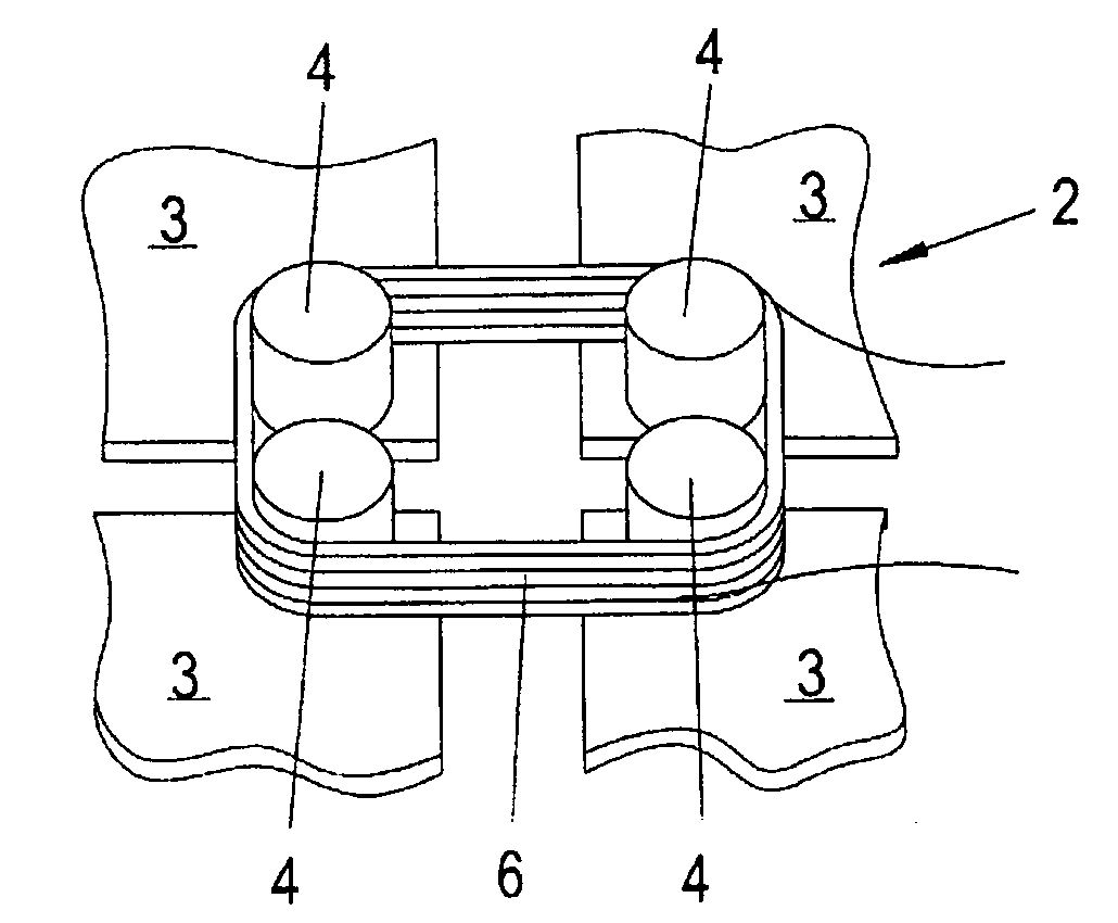
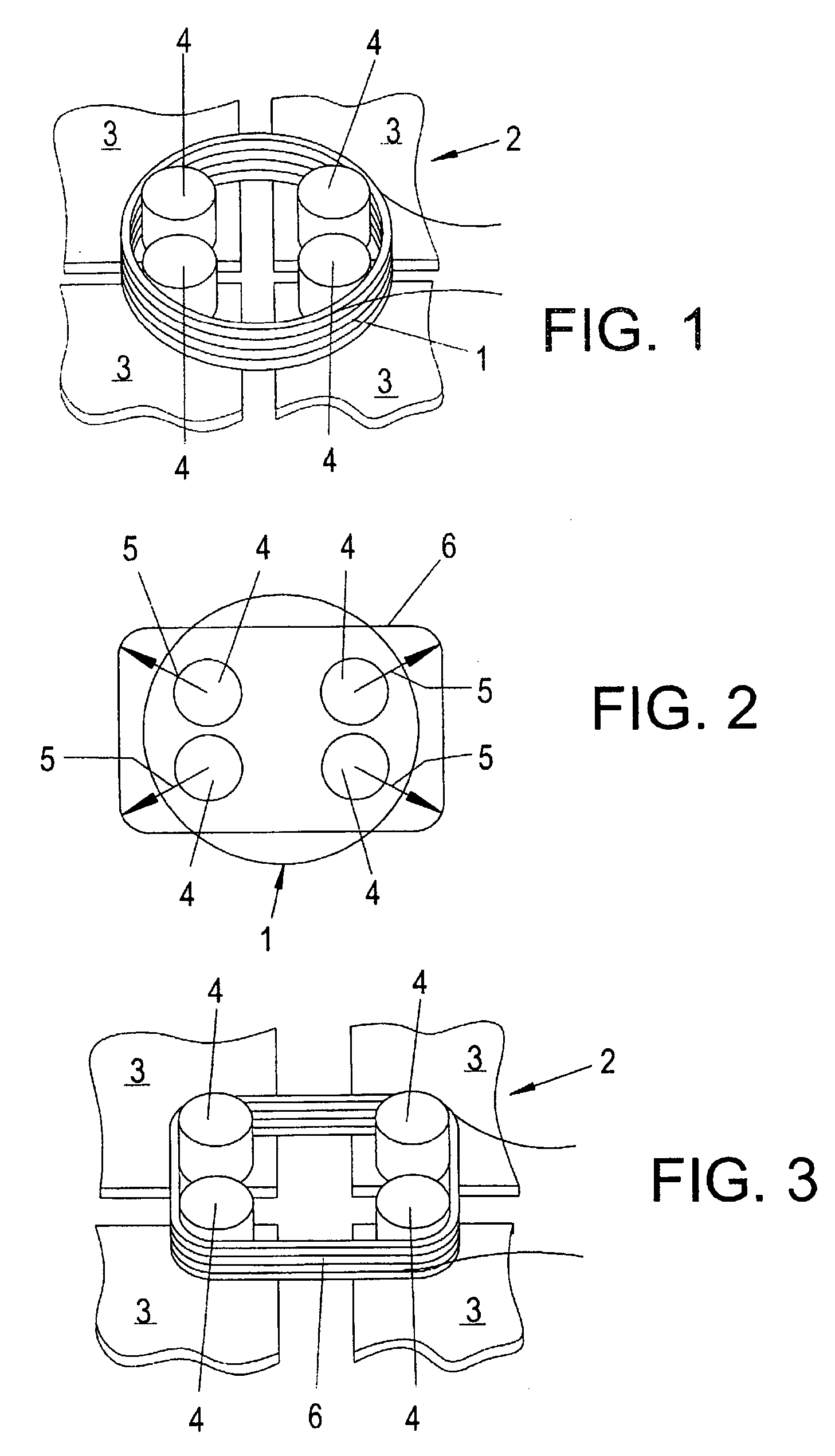
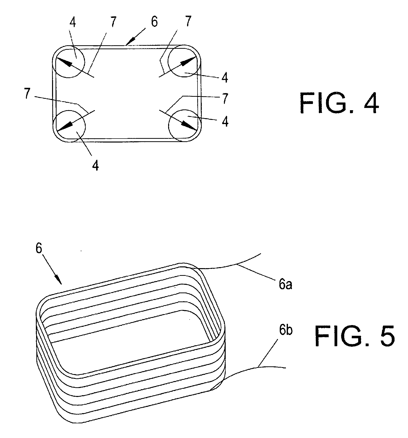
[0031] The manufacture of a moving coil for a loudspeaker with a rectangular cross section is elucidated below with the help of FIGS. 1 to 4 as an embodiment of the invention.

[0032] Such a coil shown in FIG. 5 can be advantageously used in small loudspeakers e.g. in loudspeakers for mobile telephones.

[0033] A circular cylindrical coil 1 with a cylinder axis and with a circular ring cross section is first wound by a method known to those skilled in the art. The coil 1 is then glued using an adhesive to facilitate further handling or make it possible, particularly to avoid the disintegration of the wound coil wire windings. The coil 1 can be wound, for example, from round adhesive varnish wires, which consist of copper or aluminum and have a diameter of 0.02 to 0.1 mm. It is also possible to use other types of wire.

[0034] The coil 1 obtained by winding and gluing is now placed onto an expander 2. The expander 2 in the present case has four jaws 3. Each jaw 3 has a finger 4, which i...


PUM

PropertyMeasurementUnit
diameteraaaaaaaaaa
elongationaaaaaaaaaa
shapeaaaaaaaaaa

Abstract

Method of manufacturing a coil (6) with a cross section differing from a circular ring cross section, in which method a circular cylindrical coil (1) with a circular ring cross section is first wound and then reshaped into a coil (6) with the other cross section differing from the circular ring cross section, wherein at least two axially parallel fingers (4) of an expander (2) are temporarily inserted into the coil interior for reshaping the wound circular cylindrical coil (1) and are displaced in a diverging relative movement after the insertion and while doing so expand the initially circular cylindrical coil (1) into the coil (6) with the different cross section.

Description

FIELD OF THE INVENTION [0001] The invention relates to a method of manufacturing a coil with a cross section differing from a circular ring cross section, in which method first a circular cylindrical coil with a cylinder axis and a circular ring cross section is wound and then the circular cylindrical coil is reshaped into the coil with another cross section differing from the circular ring cross section. [0002] The invention further relates to a moving coil for a loudspeaker. [0003] The invention further relates to a loudspeaker with a moving coil. BACKGROUND OF THE INVENTION [0004] Dynamic loudspeakers achieve a particularly high efficiency, if the cross section of their moving coil is adjusted to the geometry of the membrane. Especially in case of small devices, such as mobile telephones, small loudspeakers with oval or rectangular shape are preferably used. There is a special requirement here for cost-effective manufacturing methods for moving coils with cross sections that are ...

Claims


Application Information

Patent Timeline
Patent Type & Authority Applications(United States)
IPC IPC(8): H01F41/04H04R9/04
CPCH01F41/04H01F41/0612H01F41/0687H01F41/0691Y10T29/4902H04R31/00Y10T29/49071Y10T29/49073H04R9/046H01F41/064H01F41/077H01F41/098
Inventor NIERLICH, HEINZ
Owner SOUND SOLUTIONS INTERNATIONAL COMPANY LTD
Why Eureka
Try Eureka