Optical Pumping Modules, Polarized Gas Blending and Dispensing Systems, and Automated Polarized Gas Distribution Systems and Related Devices and Methods

a technology of optical pumping modules and polarized gas, which is applied in the direction of ratio control, distribution delivery, multiple way valves, etc., can solve the problems of hyperpolarized gas deteriorating or decaying relatively quickly, sensitive polarized state of gases, undetectable,

Inactive Publication Date: 2008-01-10
POLAREAN
View PDF23 Cites 9 Cited by
  • Summary
  • Abstract
  • Description
  • Claims
  • Application Information

AI Technical Summary

Benefits of technology

[0011] It is an additional object of the present invention to provide an automated hyperpolarizer that can produce polarized gases.
[0012] It is another object of the present invention to provide a hyperpolarizer that can be operated at the point-of-use.
[0022] Advantageously, the present invention can provide improved hyperpolarizers. Certain embodiments provide systems and devices that can handle polarized gas in an automated or semi-automated manner and that can produce patient-sized pharmaceutical grade quantities (such as 0.5-2 liters) of polarized gas in a manner that can reduce the labor involved therewith can be produced to support to the clinic or hospital.

Problems solved by technology

Unfortunately, as will be discussed further below, the polarized state of the gases is sensitive to handling and environmental conditions and can, undesirably, decay from the polarized state relatively quickly.
Unfortunately, both during and after collection, the hyperpolarized gas can deteriorate or decay relatively quickly (lose its hyperpolarized state) and therefore must be handled, collected, transported, and stored carefully.
Thus, handling of the hyperpolarized gases is critical, because of the sensitivity of the hyperpolarized state to environmental and handling factors and the potential for undesirable decay of the gas from its hyperpolarized state.

Method used


Image

  • Optical Pumping Modules, Polarized Gas Blending and Dispensing Systems, and Automated Polarized Gas Distribution Systems and Related Devices and Methods
  • Optical Pumping Modules, Polarized Gas Blending and Dispensing Systems, and Automated Polarized Gas Distribution Systems and Related Devices and Methods
  • Optical Pumping Modules, Polarized Gas Blending and Dispensing Systems, and Automated Polarized Gas Distribution Systems and Related Devices and Methods

Examples


Embodiment Construction

[0052] The present invention will now be described more fully hereinafter with reference to the accompanying figures, in which preferred embodiments of the invention are shown. This invention may, however, be embodied in many different forms and should not be construed as limited to the embodiments set forth herein. Like numbers refer to like elements throughout. In the drawings, layers, regions, or components may be exaggerated for clarity. In the figures, broken lines in the flow charts indicate optional features.

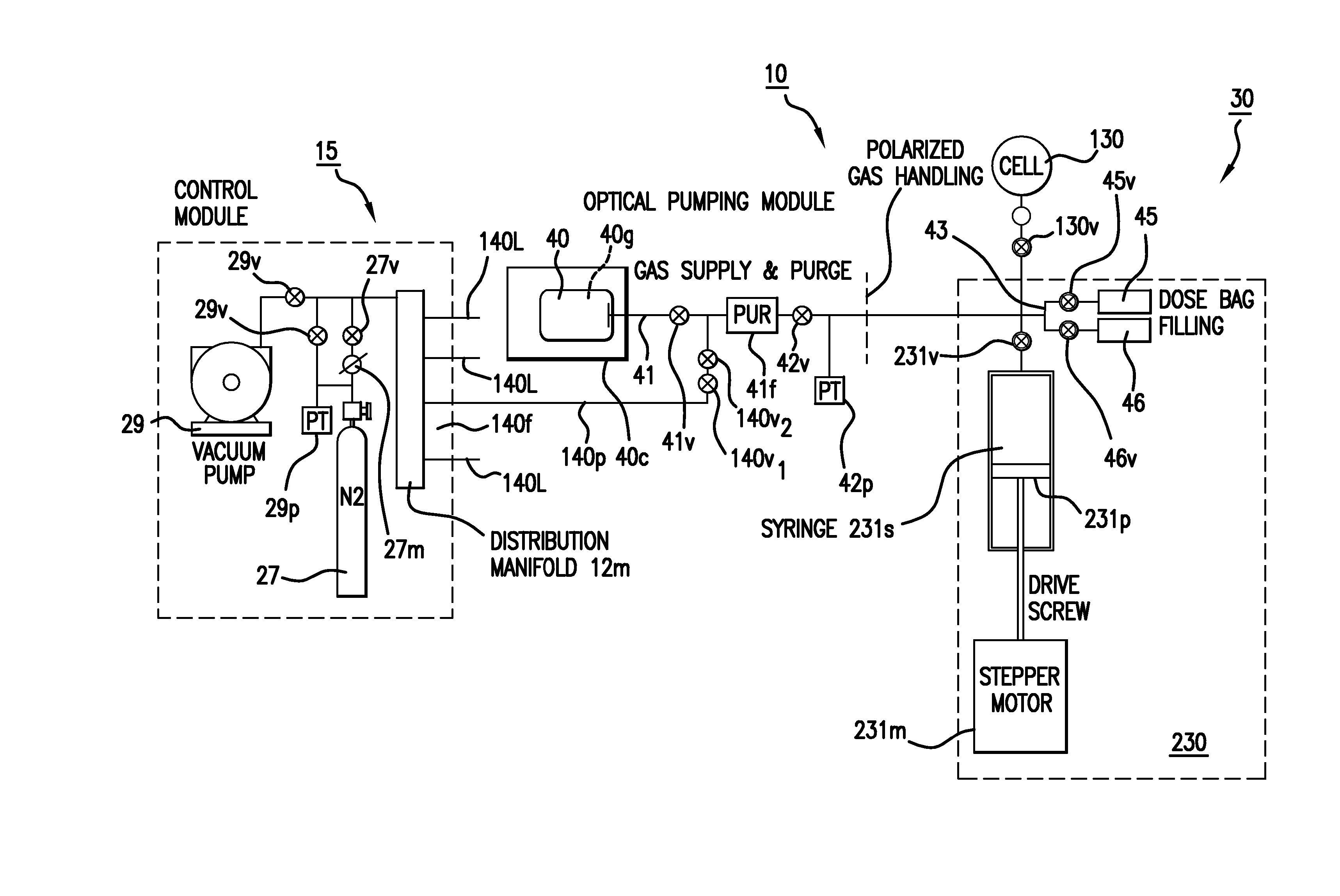
[0053] In the description of the present invention that follows, certain terms may be employed to refer to the positional relationship of certain structures relative to other structures. As used herein the term “forward” and derivatives thereof refer to the general direction the gas mixture travels as it moves through the hyperpolarizer unit; this term is meant to be synonymous with the term “downstream,” which is often used in manufacturing environments to indicate that...


PUM


Abstract

Hyperpolarizers for producing polarized noble gases can include: (a) a control module configured to direct the operation of a hyperpolarizer to produce polarized noble gas via spin-exchange interactions between a noble gas and an alkali metal; (b) at least one optical pumping module including an optical pumping cell operably associated with the control module; (c) a dispensing system operably associated with the control module and the optical pumping module to dispense meted volumes of polarized gas from the hyperpolarizer; and (d) a fluid distribution system operably associated with the control module, the optical pumping module, and the dispensing system, such that, in response to commands transmitted from the control module, the fluid distribution system operates to automatically direct purge gas into and out of a gas travel path that extends from the control module to the optical pumping cell prior to commencing the spin-exchange interactions in the optical pumping cell, then to receive unpolarized gas and direct it to travel in the gas travel path to the optical pumping cell, and, following the spin-exchange interactions, to automatically direct polarized gas from the optical pumping cell into a polarized gas exit travel path to the dispensing system. Related methods and computer program products as well as particular embodiments of optical pumping modules, thermal oven assemblies, and manifold blocks are also described.

Description

[0001] This application is a divisional of U.S. application Ser. No. 10 / 277,909 filed Oct. 22, 2002, which claims priority to U.S. application No. 60 / 335,706 filed Oct. 22, 2001, the entire disclosure of which is hereby incorporated by reference.FIELD OF THE INVENTION [0002] The present invention relates to the production of polarized noble gases used in NMR and magnetic resonance imaging (“MRI”) applications. BACKGROUND OF THE INVENTION [0003] It has been discovered that polarized inert noble gases can produce improved MRI images of certain areas and regions of the body that have heretofore produced less than satisfactory images in this modality. Polarized helium-3 (“3He”) and xenon-129 (“129Xe”) have been found to be particularly suited for this purpose. Unfortunately, as will be discussed further below, the polarized state of the gases is sensitive to handling and environmental conditions and can, undesirably, decay from the polarized state relatively quickly. [0004] Hyperpolariz...

Claims


Application Information

Patent Timeline
Patent Type & Authority Applications(United States)
IPC IPC(8): A61M16/12A61K49/18G01R33/28
CPCA61K49/1815G01R33/282Y10T436/25Y10T436/24Y10T436/25875Y10T436/10
Inventor BOLAM, KENNETH
Owner POLAREAN
Why Eureka
Try Eureka