Holster for hand held electronic device

a technology for electronic devices and holsters, which is applied in the field of holsters, can solve problems such as unintended keystrokes, trackball movement or other triggers, and devices that cannot be disabled or turned off, and can only be removed on

Inactive Publication Date: 2008-01-17
RES IN MOTION LTD
View PDF16 Cites 68 Cited by
  • Summary
  • Abstract
  • Description
  • Claims
  • Application Information

AI Technical Summary

Problems solved by technology

However, a problem which sometimes arises is that the device may not be disabled or turned off until it is fully seated in the holster, since the sensor may not come into proximity to the magnet until then.
This can result in unintended keystrokes, trackball movement or other triggers, which are clearly undesirable, while the user is placing the device in the holster without any other desired activity.
However, the device must then remain disabled once fully seated.
Another problem is that the device may not consider itself to be holstered if it is not fully seated in the holster, with the magnet aligned with the Hall effect sensor.
The device may misbehave from a user's viewpoint, for example by failing to vibrate in response to an incoming call or message, though set to vibrate when in the holster; or failing to lock, consuming excessive power via the LCD, trackball or other device feature.
The same problem can arise, especially in leather or other soft-material holsters, when the device is properly seated initially, but comes loose and rides up in the holster so that the magnet in the holster no longer aligns with the sensor in the device.

Method used


Image

  • Holster for hand held electronic device
  • Holster for hand held electronic device
  • Holster for hand held electronic device

Examples


Embodiment Construction

[0013]In the following description, various exemplary embodiments of the invention will be described. For purposes of explanation, specific configurations and details are set forth in order to provide a thorough understanding of the embodiments However, it should be apparent to those knowledgeable in the field of the invention that the invention may be practiced without the specific details. The description may also omit or simplify well-known features in order not to obscure the embodiment being described.

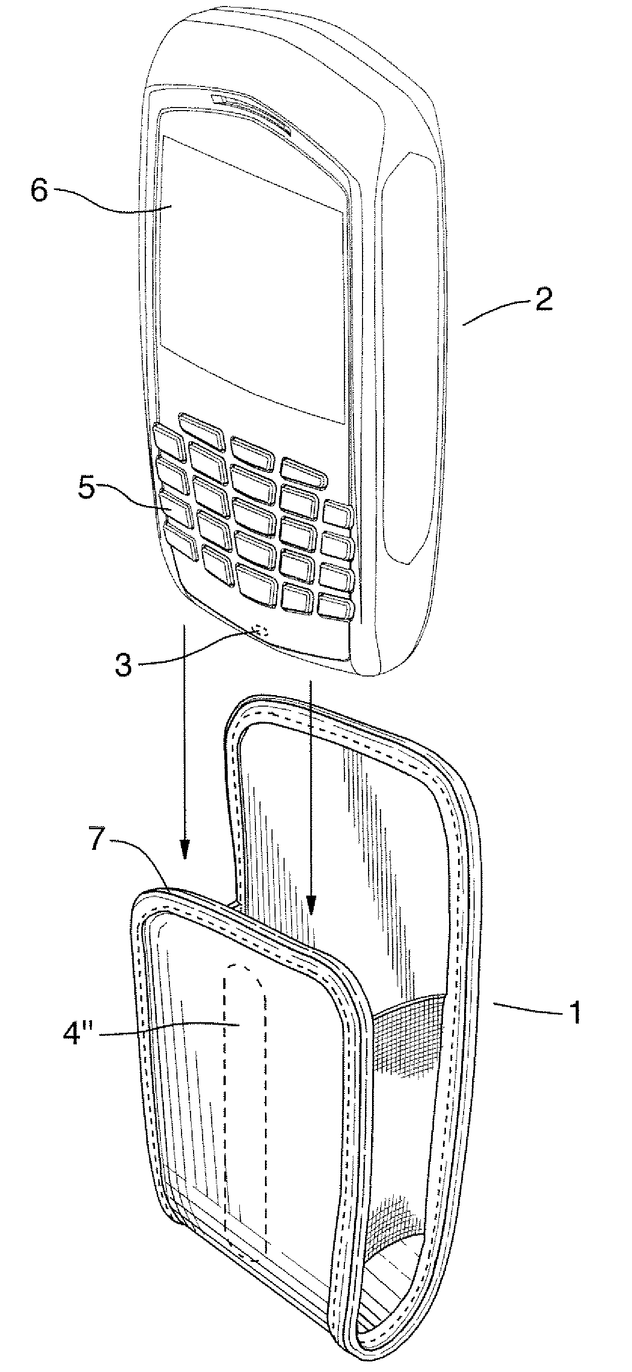
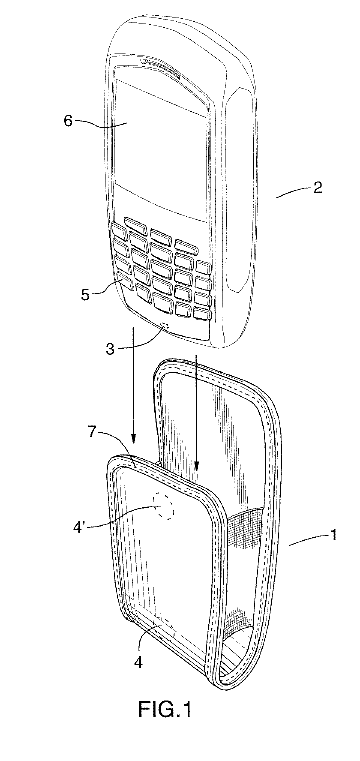
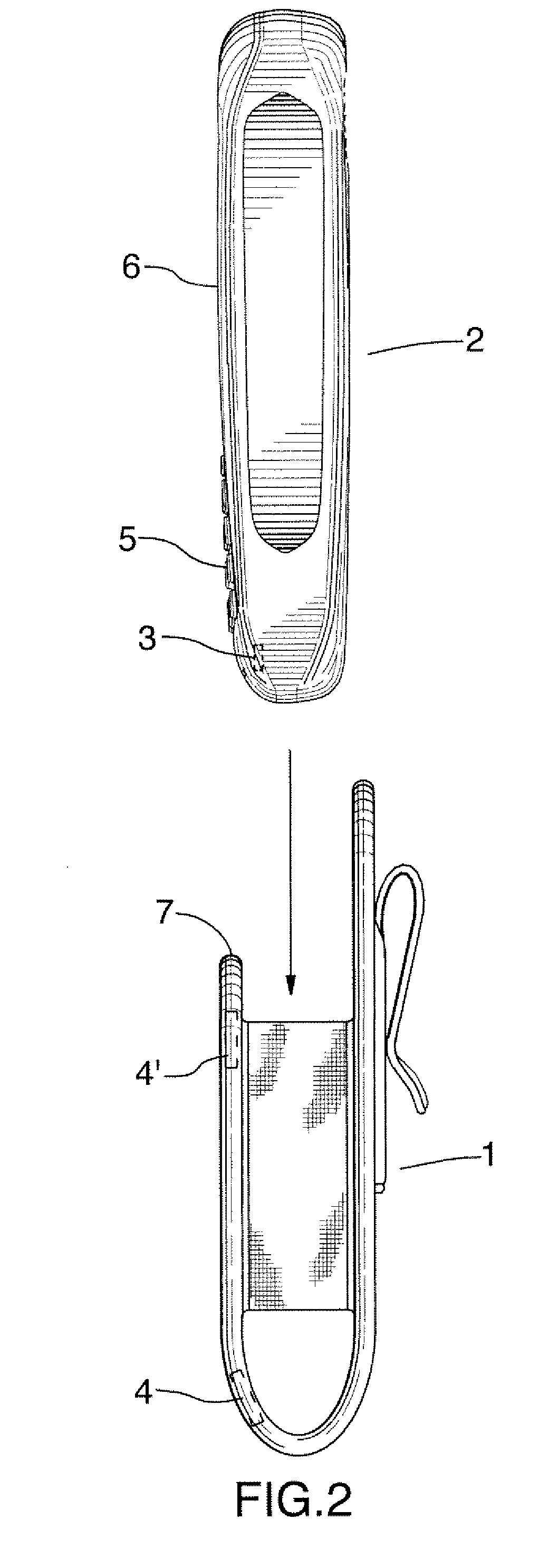
[0014]FIG. 1 shows a holster 1 for an electronic device 2, according to one aspect of the invention. The device has a Hall effect sensor 3 embodied therein and the holster has a first magnet 4 positioned to align with the sensor when the device is fully holstered. The device is programmed so that when the Hall effect sensor detects the magnet, the device is disabled, or at least certain elements thereof are disabled, for example the keyboard 5 and display 6, and other elements as ...


PUM


Abstract

The holster has one or more magnets positioned so that a Hall effect sensor in the handheld device detects a magnet both when partially inserted in the holster and when fully holstered, thereby enabling desired elements of the device to be disabled from the beginning of the holstering process, to avoid accidental keystrokes or triggering of other input elements such as a trackball. The holster may have separate magnets to accomplish this, or an elongated single magnet.

Description

BACKGROUND OF THE INVENTION[0001]This invention relates to portable handheld electronic devices, especially but not limited to portable handheld wireless communication devices, and more particularly to holsters for same in combination with the devices.[0002]With such devices, it is common and convenient to provide a holster to protect and conveniently transport the device when it is not in use. The holster may have a belt clip to attach it to a user's belt, or may have other attachment means for attachment to a purse or knapsack, or may simply be nothing more than a protective cover allowing the user to store the device in a pocket, briefcase or wherever else desired. However, the devices typically have keyboards, trackballs, touch pads, switches or other such elements, and it is desirable to be able to place the device in the holster without having to turn it off to avoid triggering of these elements when contacted by the holster. It is known to have a magnet in the holster, with a...

Claims


Application Information

Patent Timeline
Patent Type & Authority Applications(United States)
IPC IPC(8): H04M1/00G08B13/14
CPCH04M1/04A45F5/021
Inventor MAK-FAN, DAVID J.LEE, MATTHEW R.LYNCH, DANIEL G.
Owner RES IN MOTION LTD
Why Eureka
Try Eureka