
Integral Swivel Hydraulic Connectors, Door Hinges, and Methods and Systems for Their Use

a technology of hydraulic connectors and integrated swivels, applied in the direction of hinges, wing accessories, manufacturing tools, etc., can solve the problems of total system failure, reduced system performance, and reduced availability of business critical systems

Active Publication Date: 2008-01-24
VERTIV CORP
View PDF11 Cites 105 Cited by
  • Summary
  • Abstract
  • Description
  • Claims
  • Application Information

AI Technical Summary

Benefits of technology

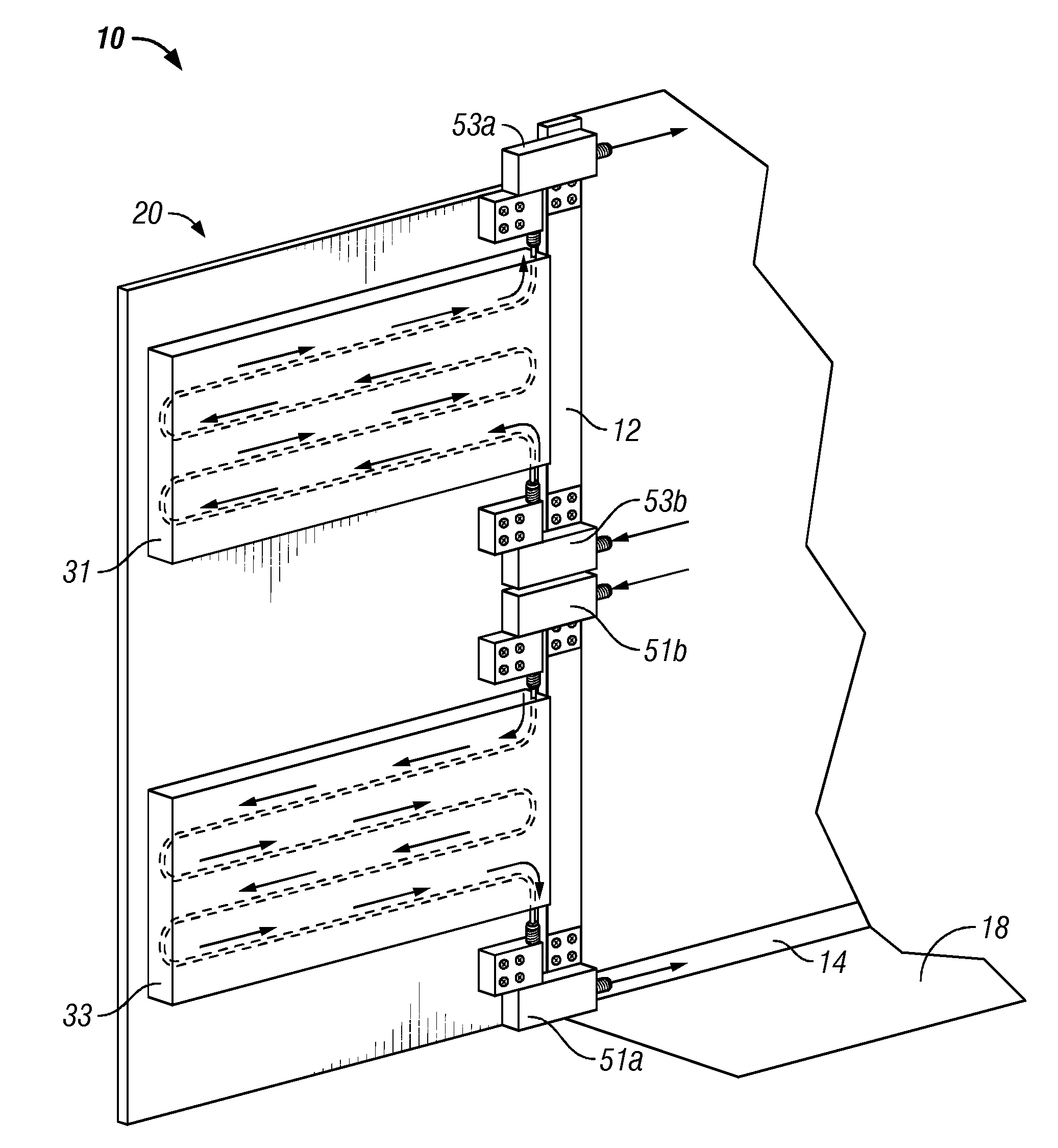
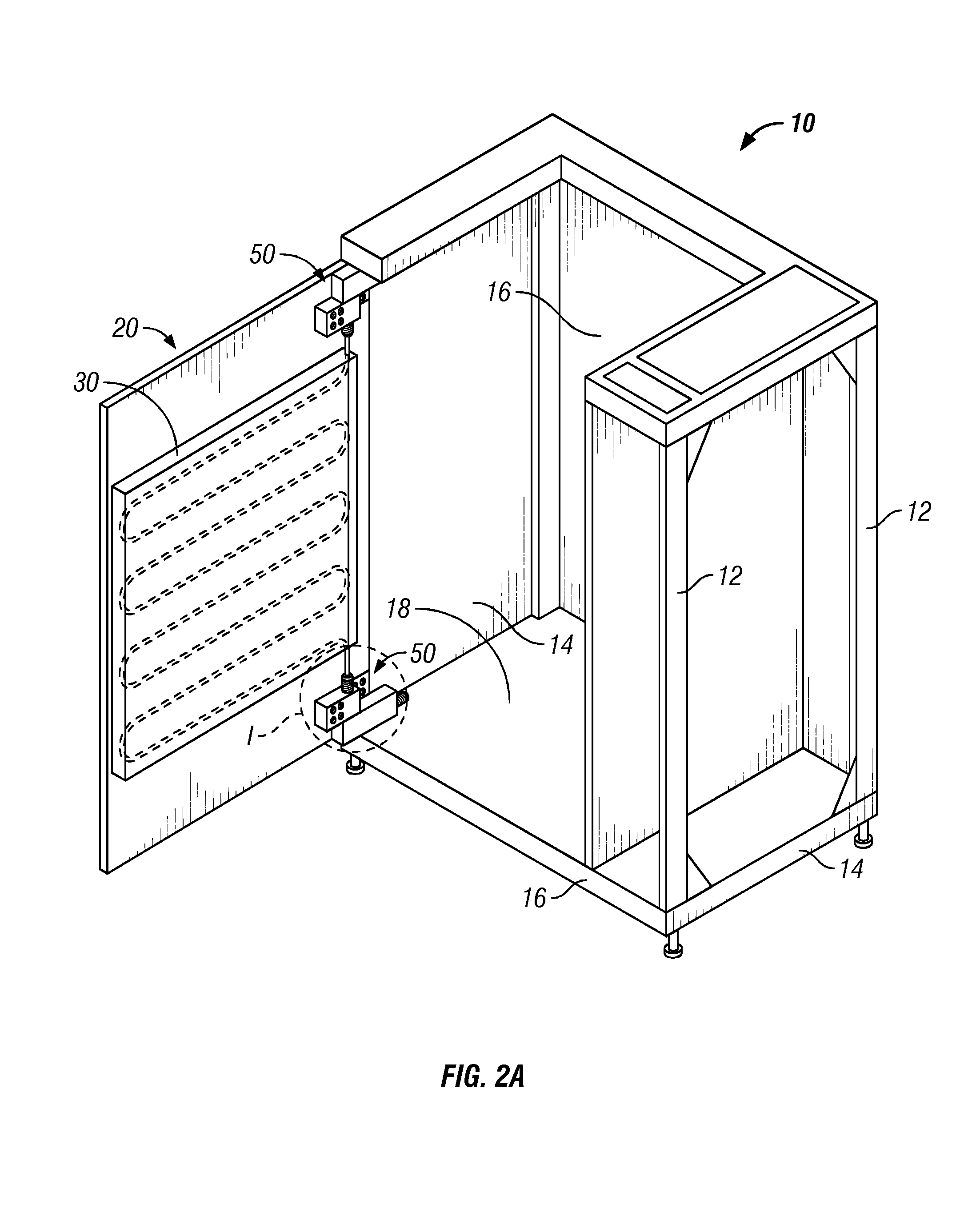
[0012]In a first aspect of the present disclosure, a swivel hinge assembly is described, wherein the swivel hinge assembly comprises a first relatively stationary base member and a second relatively stationary base member; a first swivel member having a channel extending through the body of the swivel member, the swivel member being integral with the first relatively stationary base member; a second swivel member that is integral with the second relatively stationary base member; and a channel extending through both the first swivel member and the second swivel member and providing fluid communication between the first and second swivel members. In accordance with this aspect of the disclosure, the first base member and the first swivel member include a swivel shaft and the second base member and the second swivel member including at least one aperture in which the swivel shaft is journaled for rotation. In further accordance with this aspect of the disclosure, the first swivel member can journal on the first stationary base member, and the second swivel can journal on the second stationary base member, thereby allowing for swivel rotation.

Problems solved by technology

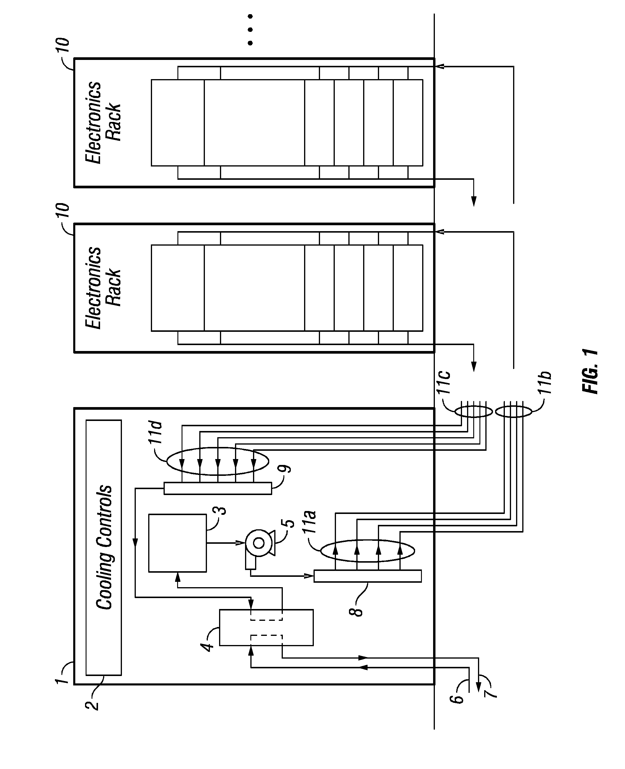
In turn, the power densities of computer systems housed in such central rooms have risen to levels that exceed the capacity of traditional approaches to cooling, thereby creating hot spots within the data center that can reduce the availability of business critical systems.
As is readily apparent, if equipment is not effectively cooled, the internal temperature of the electronic components in the equipment substantially increases, thereby leading to significantly reduced system performance and, in some cases, total system failure.
Additionally, if a cooling system inefficiently cools the equipment, either the equipment may fail due to increased operating temperature or the costs for cooling the equipment may be unnecessarily high.
While certain OEM cooling applications would benefit from having rack-mounted cooling systems, such as a cooling coil, mounted on the backside of a hardware rack, traditional mounting methods would subsequently preclude access to the equipment from the backside due to the fixed position of the coil, making any necessary access to the equipment costly both in terms of time and money, as well as resulting in potential down time for the equipment system.

Method used


Image

  • Integral Swivel Hydraulic Connectors, Door Hinges, and Methods and Systems for Their Use
  • Integral Swivel Hydraulic Connectors, Door Hinges, and Methods and Systems for Their Use
  • Integral Swivel Hydraulic Connectors, Door Hinges, and Methods and Systems for Their Use

Examples


Embodiment Construction

[0029]One or more illustrative embodiments incorporating the invention disclosed herein are presented below. Not all features of an actual implementation are described or shown in this application for the sake of clarity. It is understood that in the development of an actual embodiment incorporating the present invention, numerous implementation-specific decisions must be made to achieve the developer's goals, such as compliance with system-related, business-related, government-related and other constraints, which vary by implementation and from time to time. While a developer's efforts might be complex and time-consuming, such efforts would be, nevertheless, a routine undertaking for those of ordinary skill the art having benefit of this disclosure.

[0030]In general terms, Applicants have created a rotatable swivel hinge assembly having both fluid transfer capability as well as hinge mounting capability, allowing the hinge to be mounted to a suitable structure and simultaneously rem...


PUM


Abstract

The present disclosure describes swivel hinge assemblies for use in rotatably mounting two structures together, such that the structures are in fluid communication by way of fluid flow, as well as systems including such hinge assemblies. The swivel hinge assemblies generally comprise a fluid inlet port, a fluid outlet port, shafts surrounding the inlet and outlet ports and allowing for rotation about one or more axes, and attachment means which may be integrally formed with the shafts of the hinge assembly. In use, these assemblies eliminate the use for secondary hinges or secondary mounting hardware in attaching a door and a structure together in order to maintain fluid communication between an electronics rack and a heat exchanger mounted on the door of an electronics rack.

Description

CROSS REFERENCE TO RELATED APPLICATIONS[0001]The present application claims benefit and priority to U.S. Provisional Patent Application Ser. No. 60 / 831,489 filed Jul. 18, 2006, the contents of which are incorporated herein by reference in its entirety.STATEMENT REGARDING FEDERALLY SPONSORED RESEARCH OR DEVELOPMENT[0002]Not applicable.REFERENCE TO APPENDIX[0003]Not applicable.BACKGROUND OF THE INVENTION[0004]1. Field Of The Invention[0005]This disclosure relates generally to swivel hinge assemblies, and more particularly, to swivel hinge assemblies having integral mounting openings in the body of the swivel hinge assembly and having an interior fluid flow path, so as to provide rotatable motion via integral bearings capable of providing hingable rotation, and a hinge mounting assembly.[0006]2. Description Of The Related Art[0007]The growth of the computer industry over the past few decades has been phenomenal. The integration of these technologies, for example, in data centers and in...

Claims


Application Information

Patent Timeline
IPC IPC(8): A47B77/08E05D7/00
CPCE05D5/02E05D7/1044E05D11/00E05D11/0081E05D2003/025Y10T16/557E05Y2900/208H05K7/20645E05Y2800/10E05D5/121E05D2005/122E05Y2600/622E05D2003/027
Inventor SPEARING, IANSCHRADER, TIM
Owner VERTIV CORP
Learn More