Liquid crystal display device

a liquid crystal display and optical compensation technology, applied in non-linear optics, instruments, optics, etc., can solve the problem of remained spray alignment and looks like luminescent spot defects, and achieve the effect of luminescent spot defects

Inactive Publication Date: 2008-01-24
JAPAN DISPLAY CENT INC
View PDF2 Cites 0 Cited by
  • Summary
  • Abstract
  • Description
  • Claims
  • Application Information

AI Technical Summary

Benefits of technology

[0011]Upon ensuring transition from the spray alignment to the bend alignment, the luminescent spot defect caused by the spray alignment having remained can be avoided.

Problems solved by technology

However, there is a problem in operation of the display device that transition from the spray alignment to the bend alignment is not surely executed due to the orientation film of the counter substrate side, so that the spray alignment having remained as it is looks like a luminescent spot defect.

Method used


Image

  • Liquid crystal display device
  • Liquid crystal display device
  • Liquid crystal display device

Examples


Embodiment Construction

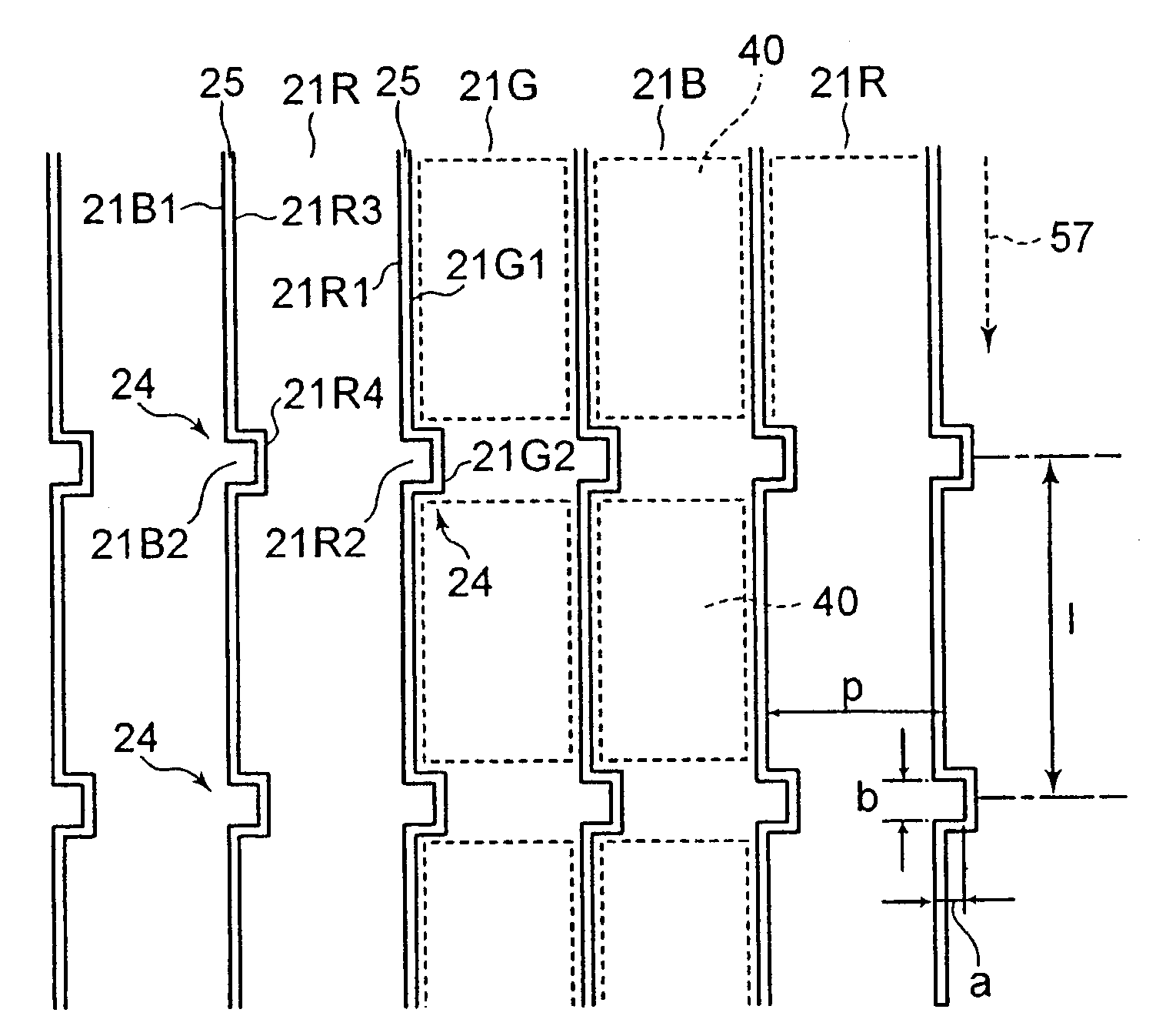
[0019]Referring to the drawings, a display device of an embodiment of the present invention will be explained hereinafter. The inventors of the present invention have focused attention on that the remaining phenomenon of the spray alignment is concerned with a minute groove pattern of the orientation film formed between stripe filters. As a result of the study achieved, we have found that fibers of the rubbing cloth do not touch the periphery of this groove so sufficiently that they rub non-uniformly the surface of the orientation film in the orientation process.

[0020]The OCB type liquid crystal display device of this embodiment is basically configured by executing rubbing process on the upper and lower substrates in parallel i.e. in the same direction.

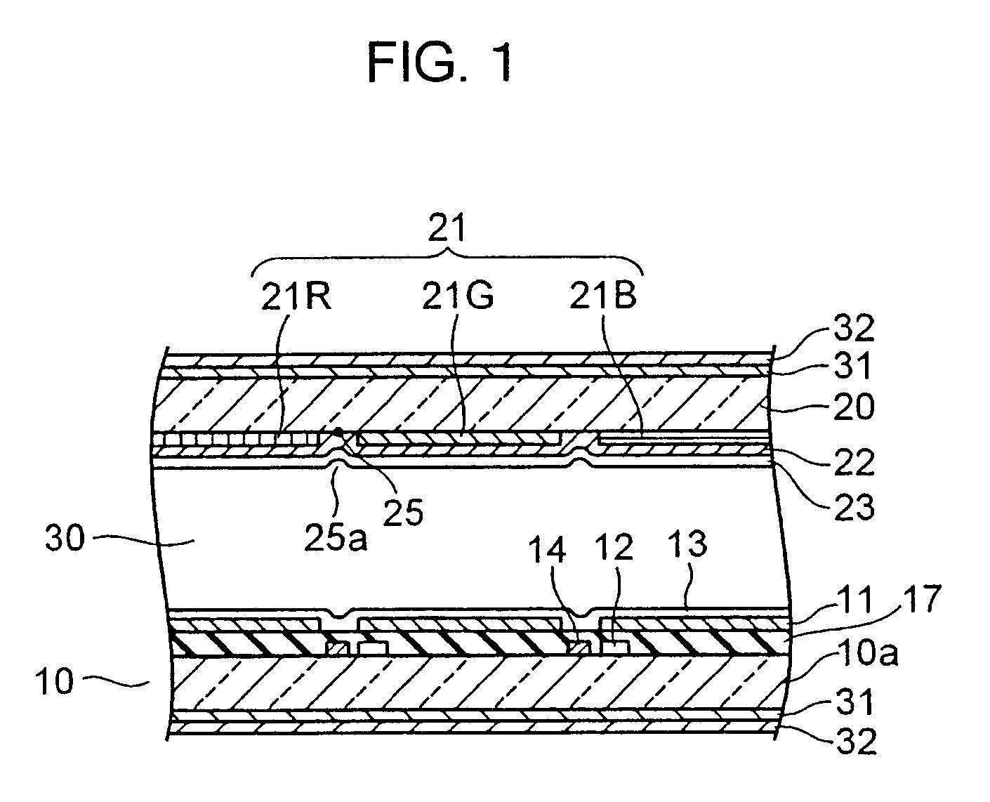
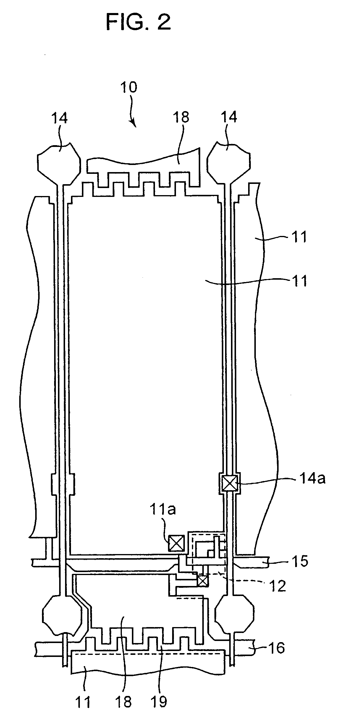
[0021]As shown in FIGS. 1 to 3, a liquid crystal panel constituting the OCB type liquid crystal display device has a configuration in which a liquid crystal layer 30 is interposed between an array substrate 10 and a counter substrate ...


PUM

PropertyMeasurementUnit
voltageaaaaaaaaaa
widthaaaaaaaaaa
widthaaaaaaaaaa

Abstract

In the optically compensated bend (OCB) type liquid crystal display device comprises a substrate 20 having a plurality of stripe-like color filters in a plurality of different colors from one another aligned in parallel with and spaced apart from each other on the substrate, a transparent electrode deposited on the color filter and an orientation film deposited on the transparent electrode, the orientation film being treated with an orientation process in a direction along a longitudinal direction of the stripe of the stripe-like color filter, and rugged portions on an edge of the color filters adjacent to each other.

Description

CROSS-REFERENCE TO RELATED APPLICATIONS[0001]This application is based upon and claims the benefit of priority from the prior Japanese Patent Applications No. 2006-195860, filed on Jul. 18, 2006 and No. 2007-177335, filed on Jul. 5, 2007; the entire contents of which are incorporated herein by reference.BACKGROUND OF THE INVENTION[0002]The present invention relates to an optically compensated bend (OCB) liquid crystal display device used for the display of liquid crystal display televisions, liquid crystal display monitors, etc.[0003]In regard to liquid crystal display devices, though the twisted nematic (TN) type liquid crystal display device has been generally used so far, the OCB type display device has been studied as a liquid crystal display device characterized in higher response (Refer to Bulletin ‘SHINGAKUGIHOU’ EDI98-144, page 199; Institute of Telecommunications Engineers, NIKKEI FLAT PANEL DISPLAY, Strategy Edition 2005, page 110).[0004]The liquid crystal is interposed be...

Claims


Application Information

Patent Timeline
Patent Type & Authority Applications(United States)
IPC IPC(8): G02F1/1335
CPCG02F1/133514G02F2001/133776G02F1/1395G02F1/13378G02F1/133776
Inventor NAKAO, KENJIKOJIMA, TETSUYA
Owner JAPAN DISPLAY CENT INC
Why Eureka
Try Eureka