
Steam cleaner and steam iron apparatus

a steam iron and steam cleaner technology, applied in the field of steam irons and steam cleaners, can solve the problems of insufficient power for the separate heating elements of the combined device, the inability of the device combining steam cleaners and steam irons to draw sufficient power, and the inability to properly operate steam generating irons. to achieve the effect of reducing the amount of power delivered to the boiler elemen

Inactive Publication Date: 2008-02-14
EURO PRO OPERATING
View PDF12 Cites 17 Cited by
  • Summary
  • Abstract
  • Description
  • Claims
  • Application Information

AI Technical Summary

Benefits of technology

The present invention is a combination steam cleaner and steam iron that includes a steam generator, a steam cleaner, and a steam iron. The steam generator includes a control device connected to a boiler element for boiling water to produce steam. The steam iron includes an iron heating element and a thermostat. The steam generator receives a maximum amount of power except when the iron thermostat is closed and the iron heating element requires power. The control device may include a circuit configured to deliver electrical power to the boiler element with a preset duty cycle, so that the reduced amount of power is a fraction of the maximum power in accordance with the duty cycle. The control device may also include a gated conductor device and a timer device, where the duty cycle is preset in accordance with values of resistances coupled to the timer device. The boiler element is preferably a 1500 watt (up to 1800 Watt) heater and the iron heating element is preferably a 600 watt heater. The invention allows for efficient use of power and provides a more effective and efficient cleaning experience.

Problems solved by technology

Steam cleaning appliances require a substantial amount of power to operate properly.
Similarly, steam generating irons require a substantial amount of power to operate properly.
Given these power constraints, a device that combines a steam cleaner with a steam iron would not be able to draw sufficient power to power the separate heating elements of the combined device.
However, the apparatus described in the '840 patent requires two separate heating elements for the boiler.

Method used


Image

  • Steam cleaner and steam iron apparatus
  • Steam cleaner and steam iron apparatus
  • Steam cleaner and steam iron apparatus

Examples


Embodiment Construction

[0024]The present invention will now be described more fully hereinafter with reference to the accompanying drawings, in which embodiments of the invention are shown. This invention may, however, be embodied in many different forms and should not be construed as limited to the embodiments set forth herein. Rather, these embodiments are provided so that this disclosure will be thorough and complete, and will fully convey the scope of the invention to those skilled in the art.

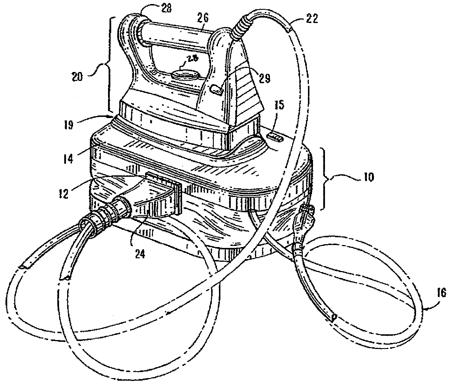
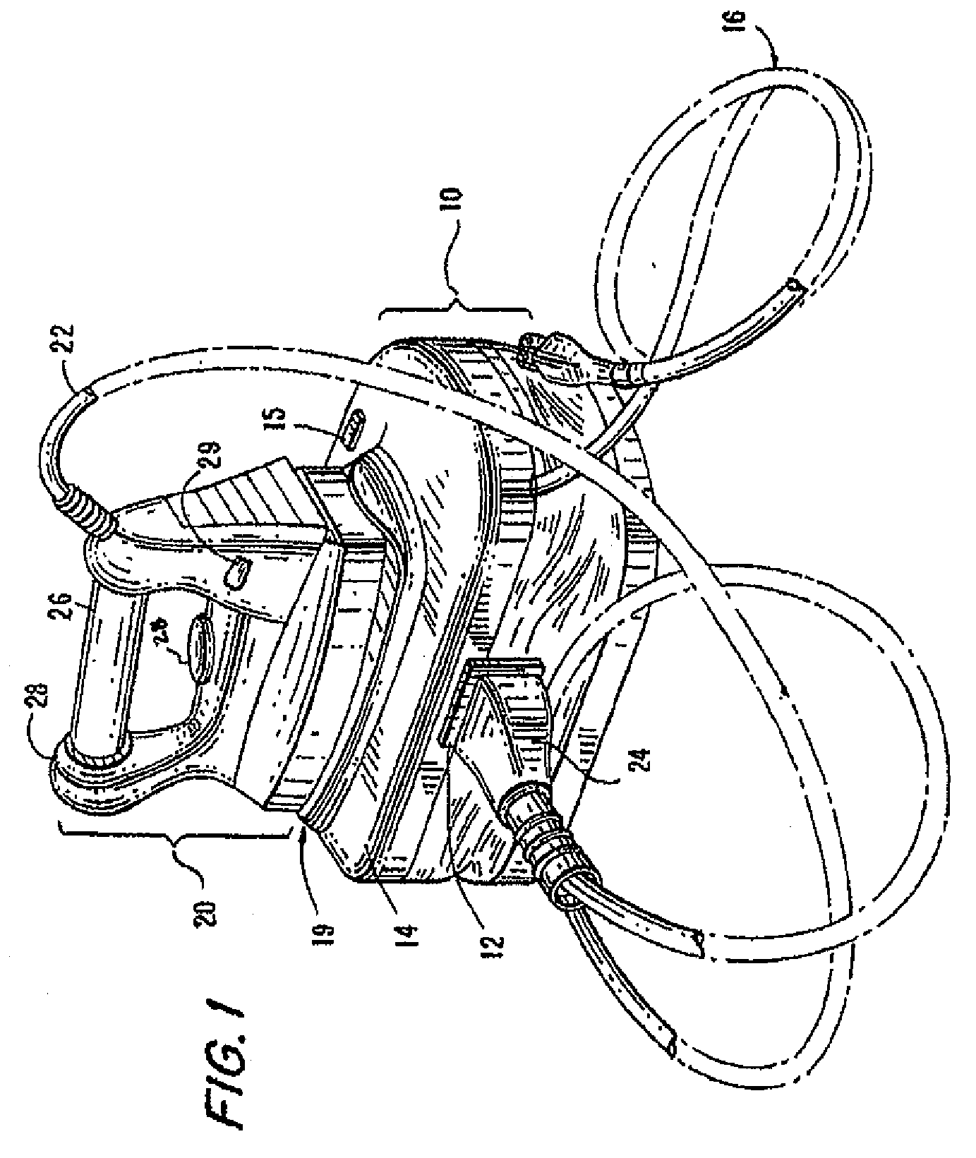
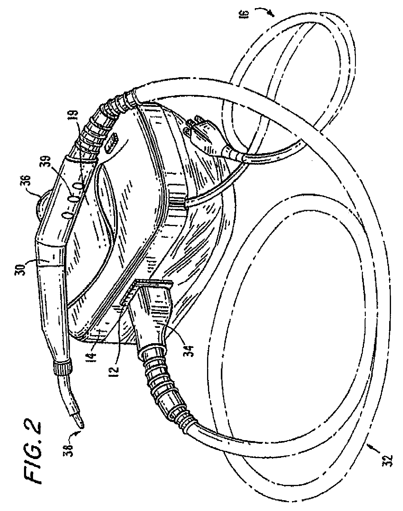
[0025]FIGS. 1 and 2 collectively illustrate a combined steam cleaner and steam iron apparatus, in accordance with an embodiment of the invention. The combined steam cleaner and steam iron apparatus includes a steam generator (boiler) unit 10, a steam iron unit 20 and a steam cleaner unit 30. Boiler unit 10 has a single heating element. FIG. 1 shows a boiler unit 10 in the base of the apparatus, with a steam iron 20 resting on top of and physically attached to the base via a steam iron hose 22. FIG. 2 shows a stea...


PUM


Abstract

A combination steam cleaner and steam iron includes a steam generator, a steam cleaner and a steam iron. The steam generator includes a control device connected to a boiler element for boiling water to produce steam. The steam iron includes an iron heating element and a thermostat. The steam generator receives a maximum amount of power except when the iron thermostat is closed and the iron heating element requires power; the amount of power delivered to the boiler element is then reduced. The control device includes a circuit configured to deliver electrical power to the boiler element with a preset duty cycle, so that the reduced amount of power is a fraction of the maximum power in accordance with the duty cycle.

Description

FIELD OF THE INVENTION[0001]The present invention relates to steam cleaners and steam irons and, more particularly, to an improved steam cleaner and steam iron apparatus.BACKGROUND OF THE INVENTION[0002]Steam cleaning appliances require a substantial amount of power to operate properly. Typically, steam cleaning appliances require around 1500 watts of power (1800 watts maximum) to sufficiently heat stored water to provide the necessary steam for the cleaning appliance.[0003]Similarly, steam generating irons require a substantial amount of power to operate properly. Steam generating irons generally include two heating elements, one to heat the iron and the other to heat water to produce steam. In the United States, the combined amount of electrical power utilized by both heating elements, for practical purposes, exceed 1800 watts due to UL regulations limiting voltage levels to 120 volts, with a maximum draw of 15 amps at this voltage level. A combined steam cleaner and steam iron in...

Claims


Application Information

Patent Timeline
Patent Type & Authority Applications(United States)
IPC IPC(8): D06F75/10
CPCD06F75/26D06F75/12
Inventor ROSENZWEIG, MAXIMILIANMCGEE, BRIAN R.VRDOLJAK, OGNJEN
Owner EURO PRO OPERATING
Learn More