Wall bracing

Inactive Publication Date: 2008-02-14
BELANGER BERT L +1
View PDF22 Cites 5 Cited by
  • Summary
  • Abstract
  • Description
  • Claims
  • Application Information

AI Technical Summary

Benefits of technology

[0009]In some embodiments a bracing system is provided for a poured in place wall including an upstanding falseworks and means for aligning the wall by anchoring the wall to the falseworks at one or mo

Problems solved by technology

As the height of the wall grows, however, bracing the forms to ensure that the cured wall is plumb becomes more challenging.

Method used


Image

  • Wall bracing
  • Wall bracing
  • Wall bracing

Examples


Embodiment Construction

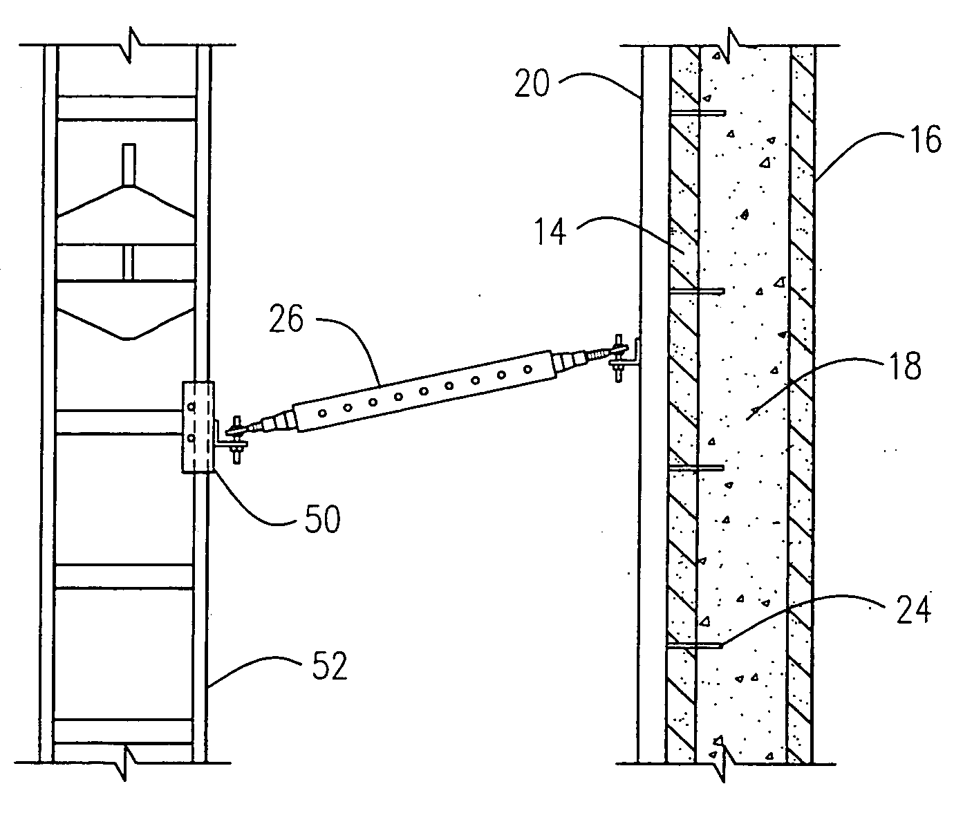
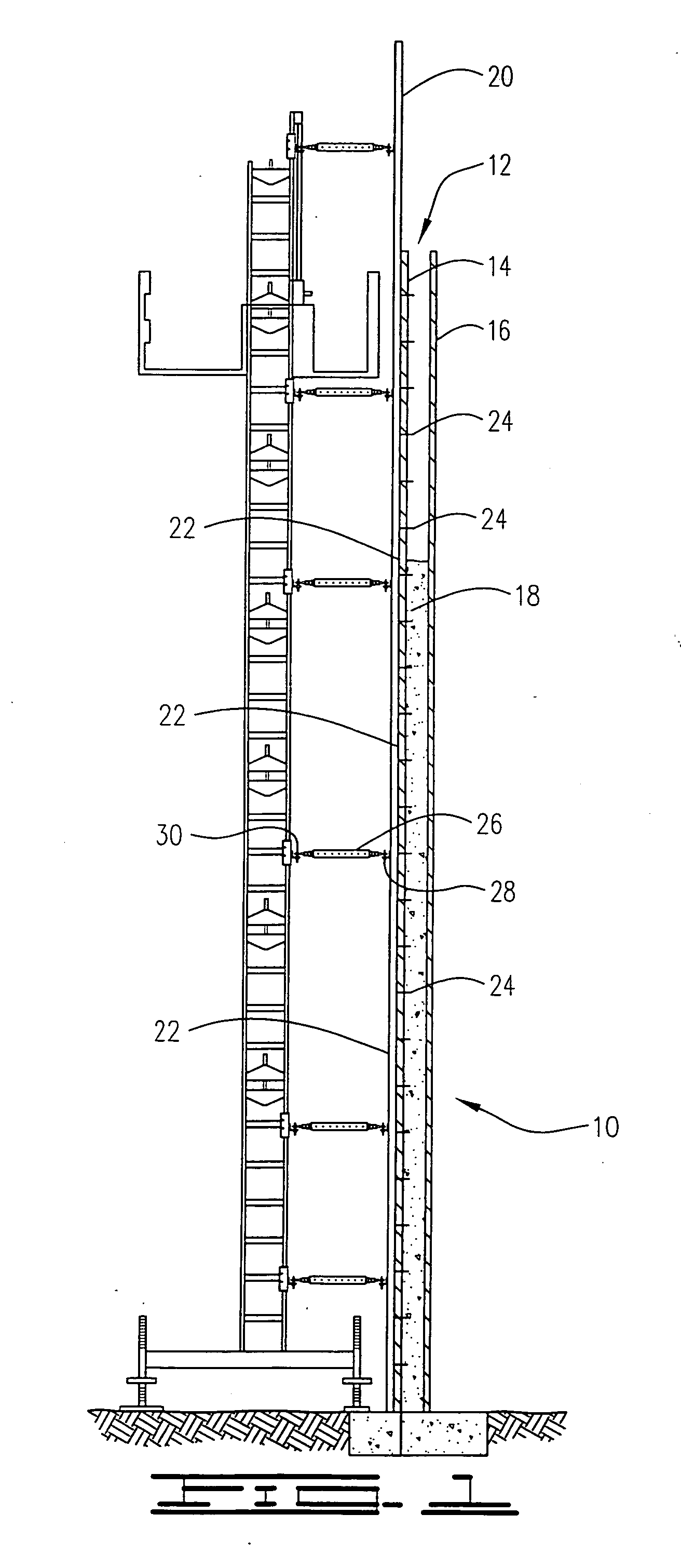
[0021]Referring to the drawings in general, and more particularly to FIG. 1 that shows a bracing system employed in the pouring in place of a wall 10. A wall form 12 is generally depicted as having spatially disposed panels 14, 16 defining a cavity therebetween for receiving pourable building material 18, such as concrete although the present embodiments are not so limited to concrete. In some embodiments the panels 14, 16 can be manifested as removable concrete forms, and in equivalent alternative embodiments the panels 14, 16 can be manifested as opposing sides of the plurality of stacked ICFs.

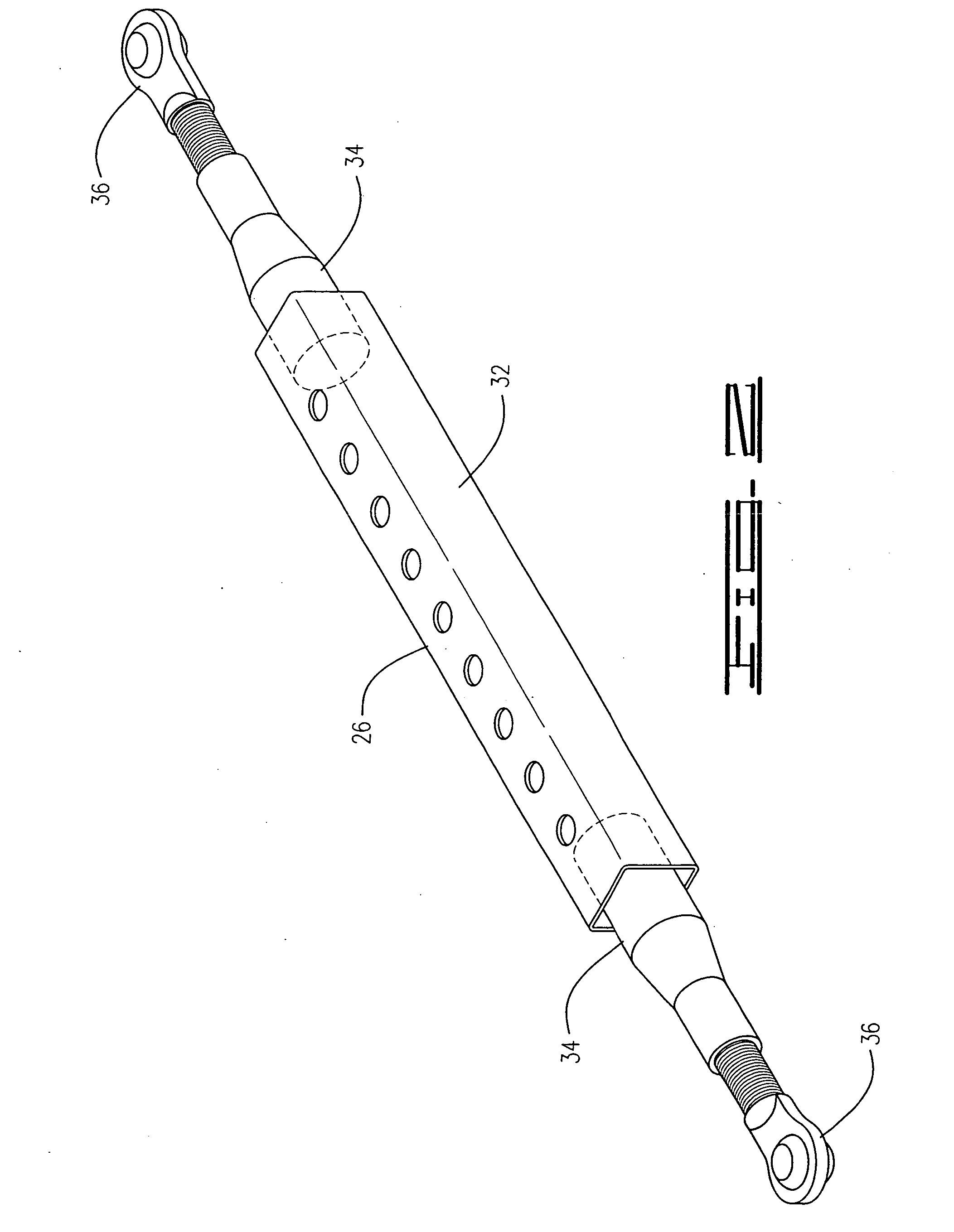
[0022]A substantially vertically disposed rail 20 is attached to the panel 14 defining a continuous bearing surface 22. The rail 20 is preferably attached to the wall form 12 by a plurality of rail fasteners 24 having a distal end that is operably disposed in the cavity and thereby embedded in the pourable material 18. This lends strength to the attachment of the rail 20. By using threaded f...


PUM


Abstract

A bracing system and associated method is provided having a wall form with spatially disposed panels defining a cavity therebetween for receiving pourable building material and a substantially vertically disposed rail attached to one of the panels defining a continuous bearing surface. An anchor has a proximal end that is positionable along the bearing surface at a plurality of different elevations and is lockingly engageable to the rail at a selected elevation of the plurality of different elevations.

Description

RELATED APPLICATIONS[0001]The present application makes a claim of domestic priority to U.S. Provisional Patent Application No. 60 / 837,107 filed Aug. 14, 2006.FIELD OF THE INVENTION[0002]The claimed invention relates generally to the field of construction and more particularly, but not by way of limitation, to an apparatus and method for vertically aligning a wall as it is built up.BACKGROUND[0003]A widely used method for constructing upstanding walls is to pour concrete in place. A poured in place wall is generally constructed by first placing forms in place and then pouring wet concrete into the form. In some instances the forms are removed after the concrete cures. In other instances an insulated concrete form (“ICF”) remains an integral part of the wall. This type of construction advantageously provides a structure that is superior to conventional framing approaches in many aspects, such as in strength and insulating capability.[0004]Technology advancements have been made in the...

Claims


Application Information

Patent Timeline
IPC IPC(8): E04G9/00
CPCE04G17/14
Inventor BELANGER, BERT L.ZERBY, RON
Owner BELANGER BERT L
Why Eureka
Try Eureka